Method and device for determining rotational rate

a technology of rotation rate and device, applied in the direction of speed measurement using gyroscopic effects, instruments, surveying and navigation, etc., can solve the problems of unwanted and serious consequences, accuracy reduction, etc., and achieve the effect of reducing effects

Active Publication Date: 2020-02-18
MOOG INC
View PDF7 Cites 0 Cited by
  • Summary
  • Abstract
  • Description
  • Claims
  • Application Information

AI Technical Summary

Benefits of technology

[0022](iv) engage the first cooperating set under step (b-iv); andbetween the fpt and the spt, the controller connects the first cooperating set to a ground-reference voltage so that radial movement of the ring is reduced.
[0059](iv) engages the first cooperating set under step (b-iv); andbetween the fpt and the spt, the controller connects the first cooperating set to a ground-reference voltage so that radial movement of the ring is reduced.

Problems solved by technology

If the heading is not accurately determined, such military vehicles may not arrive at the desired destination, which may result in unwanted and serious consequences.
Sensor bias errors, which are sometimes referred to as “offset errors”, are one type of error that can lead to a reduction in accuracy, particularly because sensor bias errors can accumulate and grow as signals derived from the angular rate information are processed, and thereby result in erroneous determinations.

Method used


Image

  • Method and device for determining rotational rate
  • Method and device for determining rotational rate
  • Method and device for determining rotational rate

Examples


Embodiment Construction

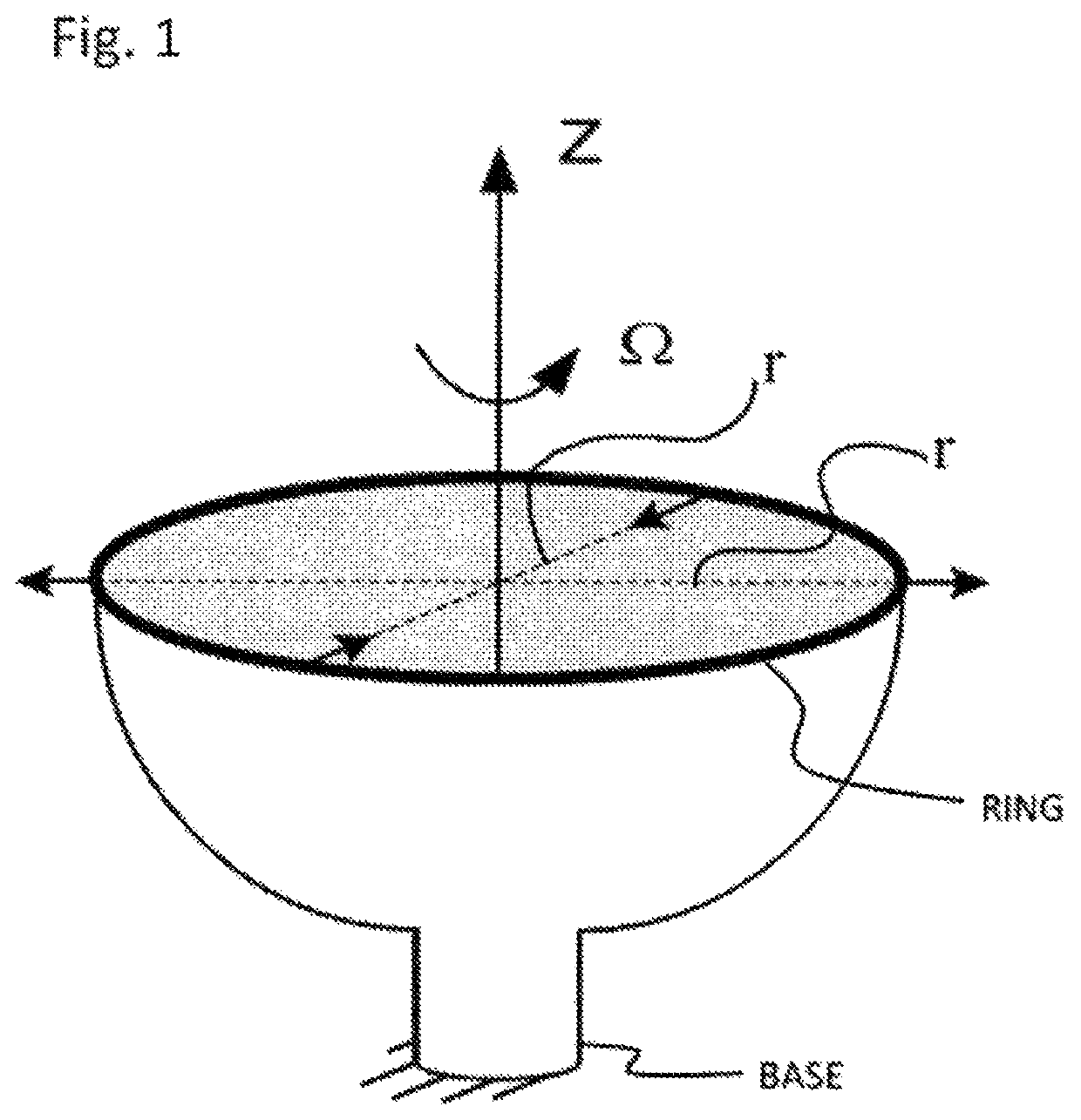
[0094]An angular rate sensor according to one embodiment of the invention operates on the “wine-glass” principle to detect angular rate. The name of this phenomenon derives from a situation in which the phenomenon was originally observed—with a wine glass. When the wine glass was struck, an audible standing-wave was created. By rotating the glass about its stem, it was heard that the standing wave rotated a fraction of the angle through which the glass was rotated.

[0095]An angular rate sensor operating on the “wine-glass” principle detects the angular position of a standing wave, and seeks to keep the standing wave in a desired stationary position. Measurements corresponding to the force that is needed to keep the wave in that desired stationary position are detected by the sensor, and those measurements are used to determine the rate at which the sensor is rotating. Toward that end, the angular rate sensor may be fabricated to have a base, a ring structure, and a means by which the...


PUM


Abstract

An angular rate sensor has a ring, a plurality of sensor-drivers, circuitry, a controller, an energy sensor, and an output signal generator. The sensors-drivers may be capacitors, inductors, or a sensor having a piezoelectric material. The sensor-drivers each have a component that vibrates along with the ring, and the sensor-drivers are arranged in cooperating sets, each cooperating set having two sensor-drivers positioned 180° apart. The circuitry can selectively engage some of the cooperating sets as sensors and others of the cooperating sets as drivers. Those sets used as sensors sense motion of the ring. Those sets used as drivers apply forces to the ring. Some of the drivers cause the ring to vibrate at its natural frequency, and some of the drivers seek to inhibit motion of the ring at particular locations. Locations at which drivers seek to inhibit motion are those locations that would be nodes in the absence of angular motion.

Description

CROSS-REFERENCE TO RELATED APPLICATION[0001]This application claims the benefit of priority to U.S. provisional patent application Ser. No. 62 / 280,730, filed on Jan. 20, 2016, which is incorporated herein by reference.FIELD OF THE INVENTION[0002]The present invention relates to devices / systems / methods of determining a rate of rotation.BACKGROUND OF THE INVENTION[0003]Angular rate measurement systems are used in many situations where it is useful to measure and determine a rate of rotation. For example, an angular rate measurement system may be useful for determining the rate of rotation of a vehicle, such as an airplane, truck, or car for purposes of determining the direction in which the vehicle is heading. Or, an angular rate measurement system may be useful for determining the rate of rotation of a cell phone which is being carried by such a vehicle. Such angular rate information may be used in a vehicle stability control system, navigation system, or elsewhere. For some angular ...

Claims


Application Information

Patent Timeline
Patent Type & Authority Patents(United States)
IPC IPC(8): G01C19/5691G01C19/5776G01C19/5677
CPCG01C19/5677G01C19/5776G01C19/5691
Inventor TRACY, MICHAELTURON, MARTINTAT, DEREK
Owner MOOG INC
Why Eureka
Try Eureka