Mapping image display control device, method, and program

a control device and image technology, applied in image enhancement, instruments, applications, etc., can solve the problems of incorrect recognition of bronchial path, low accuracy of bronchial path based on image processing, and end of graph structure may bend in an unnatural direction

Active Publication Date: 2020-02-25
FUJIFILM CORP
View PDF28 Cites 0 Cited by
  • Summary
  • Abstract
  • Description
  • Claims
  • Application Information

AI Technical Summary

Benefits of technology

In view of the circumstance described above, an object of the present invention is to provide a mapping image display control device, method, and a computer readable non-transitory recording medium storing a program that can simulate, at a high accuracy, positions on the lung surface at which dye seeps if the dye is sprayed into the peripheries of bronchi and generate and display a mapping image in which the positions are mapped.
In addition, in the mapping image display control device according to the aspect of the present invention, the display control unit can set a region including a reaching position identified by the reaching position information, can generate a mapping image in which the region is mapped to the surface of the lung region, and can cause the display unit to display the mapping image.

Problems solved by technology

However, when the extraction accuracy of a bronchial path based on image processing is low, the bronchial path is incorrectly recognized.
As a result, the end of the graph structure may bend in an unnatural direction.
In such a case, since an extending direction of the end of the graph structure also becomes unnatural and is different from an actual extending direction of the bronchus region, a to-be-stained position on the lung surface cannot be simulated at a high accuracy.

Method used


Image

  • Mapping image display control device, method, and program
  • Mapping image display control device, method, and program
  • Mapping image display control device, method, and program

Examples


Embodiment Construction

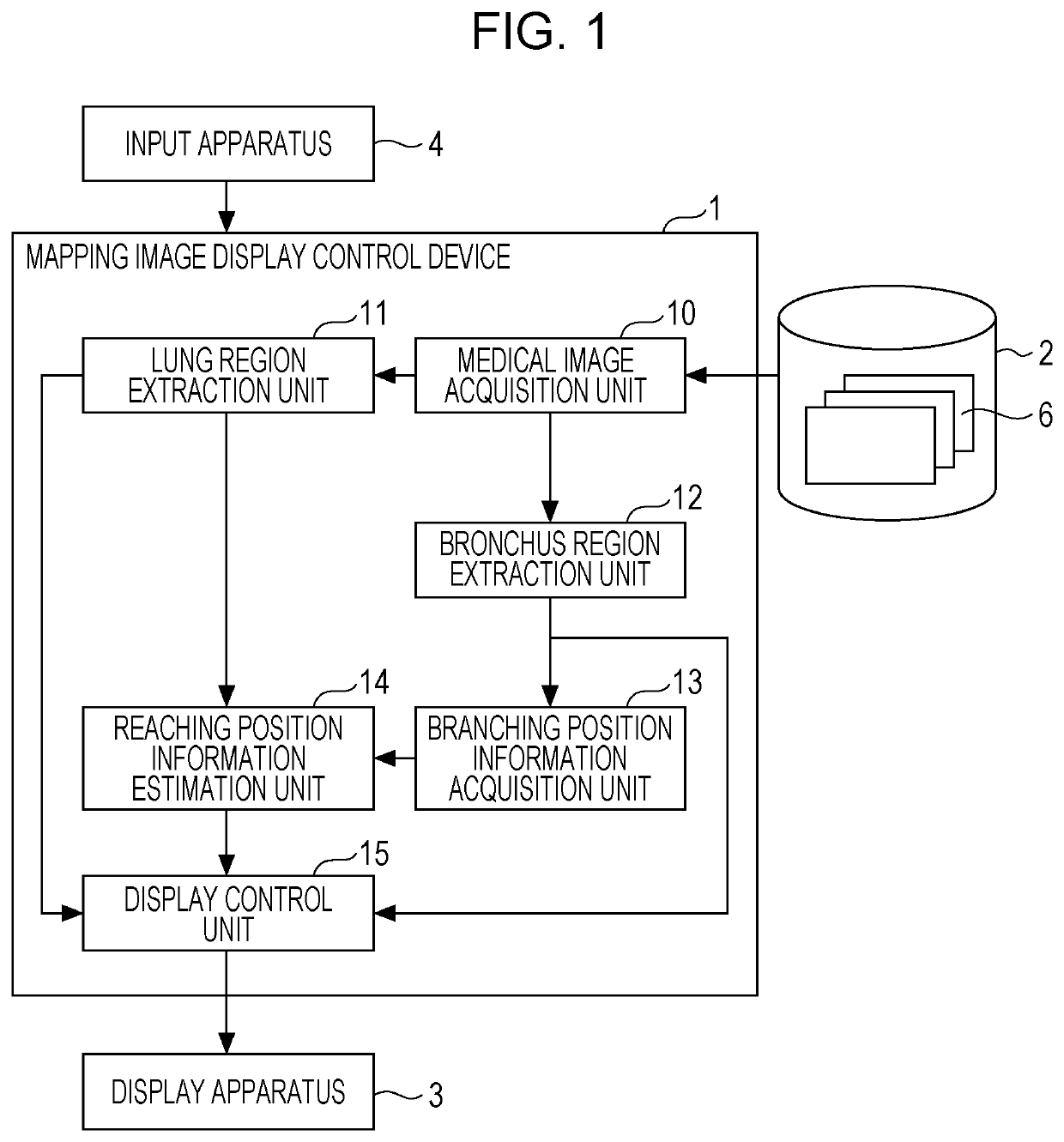
A medical-image-diagnosis assisting system that uses an embodiment of a mapping image display control device, method, and a recording medium storing a program according to the present invention will be described in detail below with reference to the drawings. FIG. 1 is a block diagram illustrating a schematic configuration of the medical-image-diagnosis assisting system according to the embodiment.

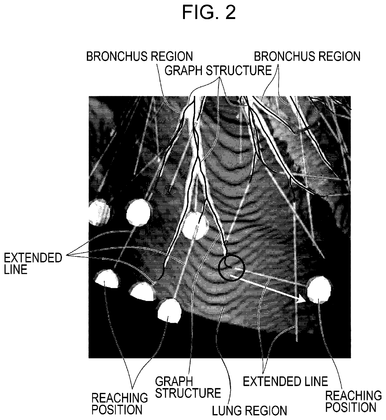
The medical-image-diagnosis assisting system according to the embodiment assists doctors when the doctors perform VAL-MAP described above. Specifically, the medical-image-diagnosis assisting system according to the embodiment simulates positions on the lung surface at which dye seeps if the dye is sprayed into the peripheries of bronchi and generates and displays a mapping image in which the positions are mapped to the lung surface. Since observation of this mapping image allows doctors to grasp which position on the lung surface the dye seeps if a bronchus is selected and the dye is spray...


PUM


Abstract

A mapping image display control device includes a lung region extraction unit 11 that extracts a lung region included in a three-dimensional image, a bronchus region extraction unit 12 that extracts a bronchus region included in the lung region, a branching position information acquisition unit 13 that acquires information about a branching position of the bronchus region, a reaching position information estimation unit 14 that estimates reaching position information about a position at which an extended line of a branch included in the bronchus region reaches a surface of the lung region on the basis of the information about the branching position, and a display control unit 15 that generates a mapping image in which the reaching position information is mapped to the surface of the lung region and that causes a display apparatus 3 to display the mapping image.

Description

BACKGROUND OF THE INVENTION1. Field of the InventionThe present invention relates to a device, method, and a computer readable non-transitory recording medium storing a program for simulating positions on the lung surface at which dye seeps if the dye is sprayed into the peripheries of bronchi and for generating and displaying a mapping image in which the positions are mapped to the lung surface.2. Description of the Related ArtVAL-MAP (Virtual Assisted Lung Mapping) has been recently proposed as a method for marking a resection region of the lung (see Masaaki Sato and eight others, “Thoracoscopic wedge lung resection using virtual-assisted lung mapping”, [online], Jun. 12, 2014, Asian Cardiovascular and Thoracic Annals, <URL:http: / / aan.sagepub.com / content / early / 2014 / 06 / 12 / 0218492314539332>). In VAL-MAP, each bronchus located near a tumor is selected in a given manner and a bronchoscopic procedure is performed in the bronchus. Then, a catheter is advanced up to the periphery...

Claims


Application Information

Patent Timeline
Patent Type & Authority Patents(United States)
IPC IPC(8): A61B34/00G06T7/187A61B6/00G06T19/20G06T7/00G06T7/11G06T17/00A61B17/00A61B34/10A61B34/20A61B6/03A61B5/055
CPCG06T17/00A61B34/20A61B6/466G06T19/20A61B34/10A61B6/481A61B6/50G06T7/0012G06T7/11A61B34/25A61B6/5217G06T7/187A61B5/055G06T2200/04A61B2034/2065G06T2207/30061G06T2207/10081G06T2207/10088A61B6/4405A61B2034/104A61B2017/00809A61B2034/105A61B6/032G06T2207/10024G06T2207/30096G16H50/30
Inventor YAMADA, KENTA
Owner FUJIFILM CORP
Why Eureka
Try Eureka