
Lens driving unit, camera module, and optical instrument

a technology of lens driving unit and camera module, which is applied in the direction of instruments, printers, cameras, etc., can solve the problems of disadvantageous disconnection of coil lines when the bobbin moves, fpcb is separated in response, and the conventional lens driving device, so as to prevent a coil disconnection and prevent an erroneous operation. , the effect of enhancing product reliability

Active Publication Date: 2020-02-25
LG INNOTEK CO LTD
View PDF10 Cites 2 Cited by
  • Summary
  • Abstract
  • Description
  • Claims
  • Application Information

AI Technical Summary

Benefits of technology

Through the present invention, an adhesive force of an adhesive to a base can be improved whereby an adhesive force between a substrate portion and the base can be enhanced. Thus, a phenomenon can be prevented of the substrate portion being separated from the base under high temperature and high moisture environments during adhesive curing works between the substrate portion and the base.
The present invention can obtain an auto focus adjustment function and enhance the product reliability as a result thereof by preventing a coil disconnection by changing a position of soldering between a support member and a lead cable.
Furthermore, the present invention can prevent in advance a structural interference from generation between a support member and a lens driving device to prevent an erroneous operation and to reduce a rejection rate of products.

Problems solved by technology

However, the conventional lens driving device suffers from disadvantages in that the FPCB is separated in response to environments such as high temperature and high humidity.
Furthermore, the conventional lens driving device is configured such that a coil arranged at a bobbin is electrically connected to a spring coupled to the bobbin, where a lead line of coil may be disadvantageously disconnected when the bobbin moves.

Method used


Image

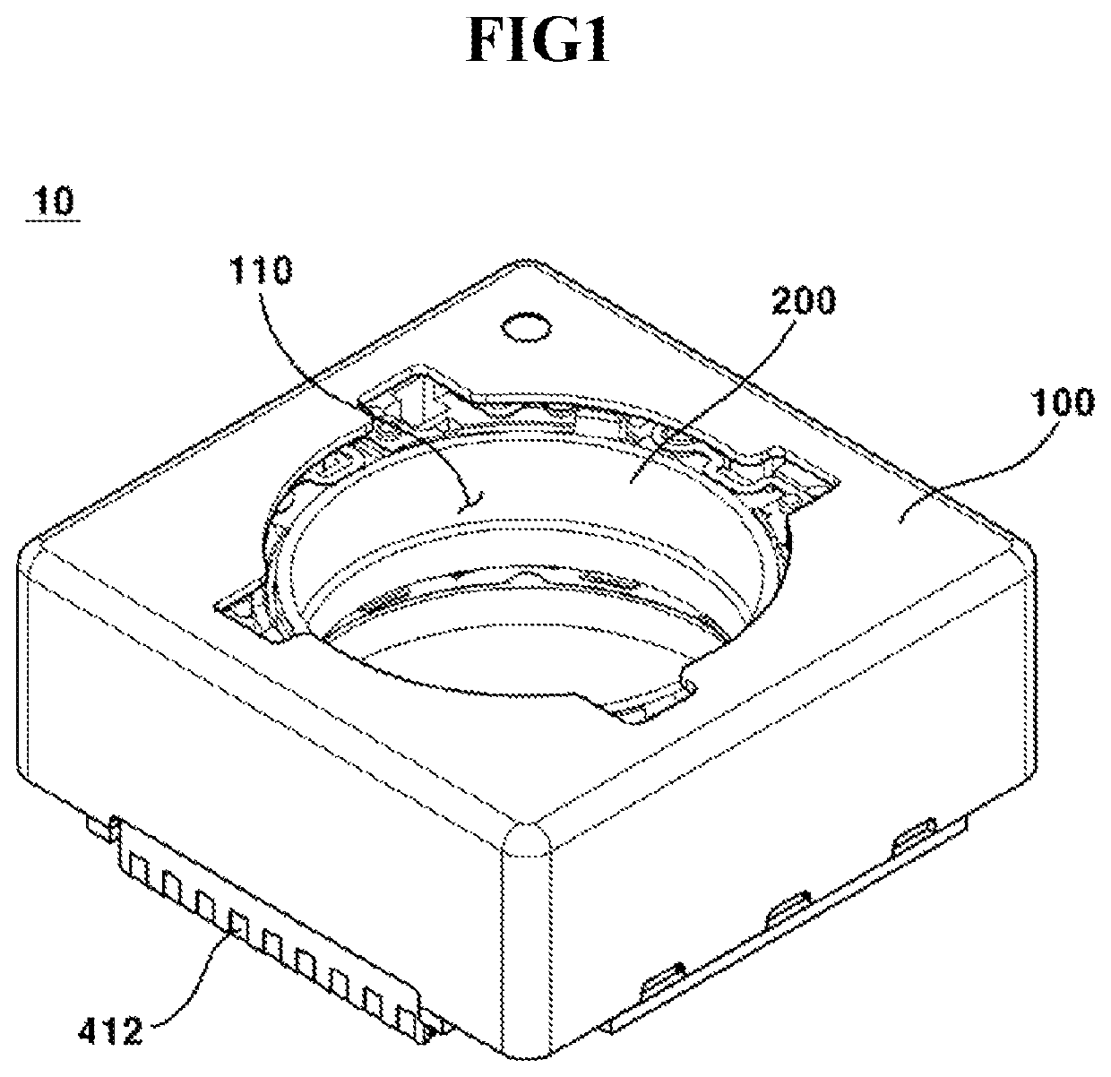
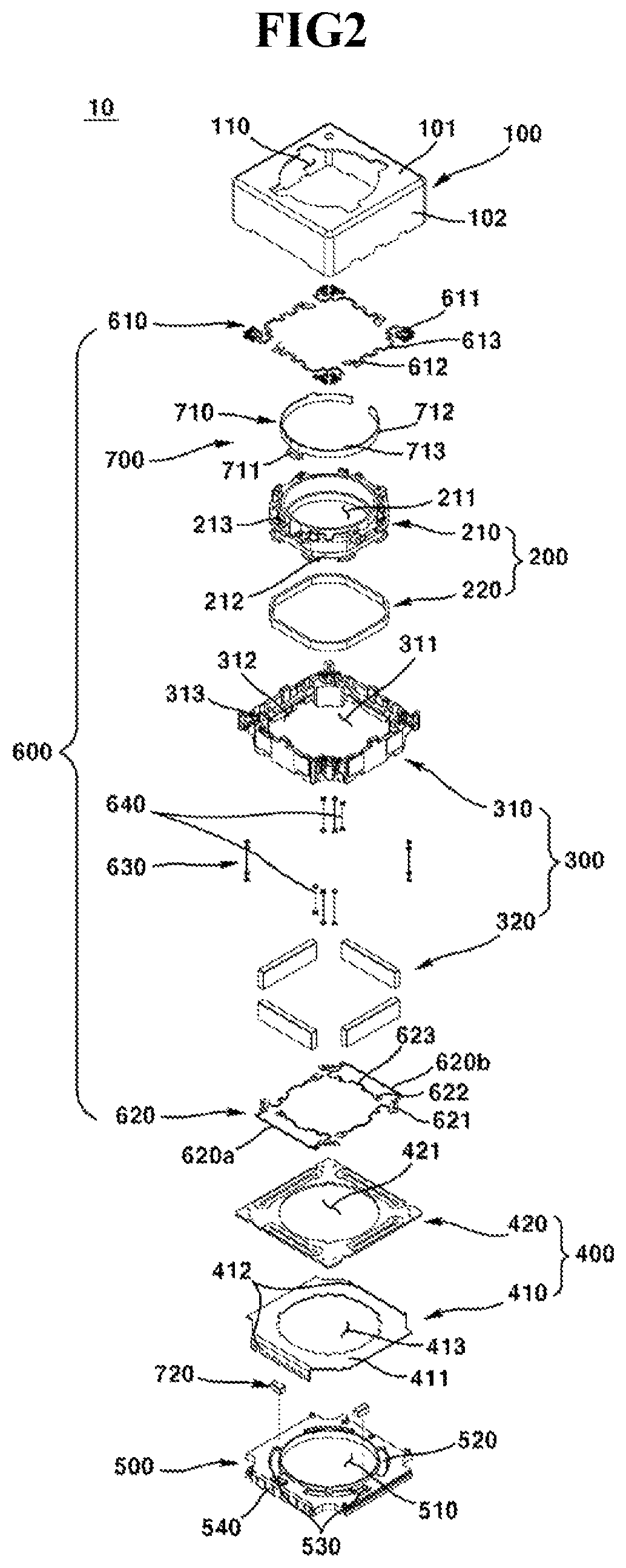
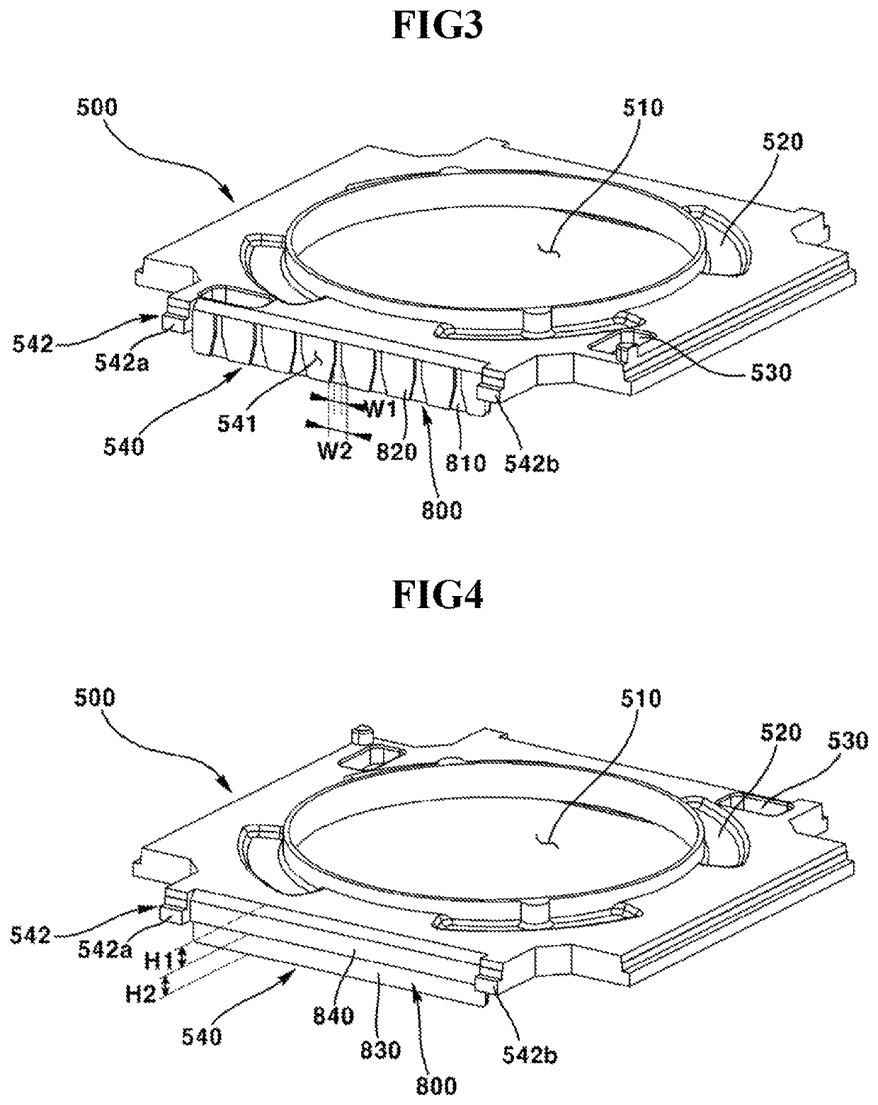
  • Lens driving unit, camera module, and optical instrument
  • Lens driving unit, camera module, and optical instrument
  • Lens driving unit, camera module, and optical instrument

Examples


Embodiment Construction

Technical Subject

Exemplary embodiments of the present invention provide a lens driving device improved in adhesive strength between a substrate part and a base. Furthermore, exemplary embodiments of the present invention provide a camera module and an optical instrument. Furthermore, exemplary embodiments of the present invention provide a lens driving unit, a camera module, and an optical instrument that prevent coil disconnection due to cantilever when a spring and a lead line of coil are soldered. Furthermore, exemplary embodiments of the present invention provide a lens driving unit, a camera module, and an optical instrument that prevent in advance generation of structural interference between a leaf spring and a lens driving device when a soldering position between the leaf spring and the lead line changes.

Technical Solution

In one general aspect of the present invention, there is provided a lens driving device comprising: a housing; a bobbin disposed in the housing; a magnet d...


PUM

PropertyMeasurementUnit
angleaaaaaaaaaa
widthaaaaaaaaaa
elasticaaaaaaaaaa

Abstract

The present embodiment relates to a lens driving device comprising: a housing; a bobbin disposed inside the housing; a magnet disposed in the housing; a first coil which is disposed in the bobbin, and is opposite to the magnet; a base disposed on the lower side of the housing; a substrate portion comprising a body portion, which is disposed on the upper surface of the base, and a terminal portion extending toward the lower side of the body portion; a terminal portion accommodating portion which is formed on a side surface of the base and accommodates at least a part of the terminal portion; and an adhesive accommodating groove which is formed in the terminal portion accommodating portion and accommodates at least a part of an adhesive contacting the terminal portion and the terminal portion accommodating portion.

Description

CROSS-REFERENCE TO RELATED APPLICATIONSThis application is the U.S. national stage application of International Patent Application No. PCT / KR2016 / 009679, filed Aug. 31, 2016, which claims priority to Korean Application Nos. 10-2015-0123072, filed Aug. 31, 2015; and 10-2015-0135359, filed Sep. 24, 2015, the disclosures of each of which are incorporated herein by reference in their entirety.TECHNICAL FIELDThe teachings in accordance with exemplary and non-limiting embodiments of this invention relate generally to a lens driving unit, a camera module, and an optical instrument.BACKGROUND ARTThis section provides background information related to the present disclosure, which is not necessarily prior art.Concomitant with widely generalized dissemination of various mobile terminals and commercialization of wireless Internet services, demands by consumers related to mobile terminals are diversified to prompt various types of circumferential devices or additional equipment to be mounted on...

Claims


Application Information

Patent Timeline
Patent Type & Authority Patents(United States)
IPC IPC(8): H04N5/225
CPCH04N5/2254G02B7/08G03B5/00G02B27/646G03B3/10G03B2205/0069G03B2205/0007H04N23/54H04N23/57H04N23/55H04N23/687
Inventor KIM, JUNG CHEOLHAN, JIN SUKPARK, SANG OKMIN, SANG JUNSON, BYUNG WOOKYOO, KYOUNG HOJUNG, TAE JIN
Owner LG INNOTEK CO LTD
Learn More