

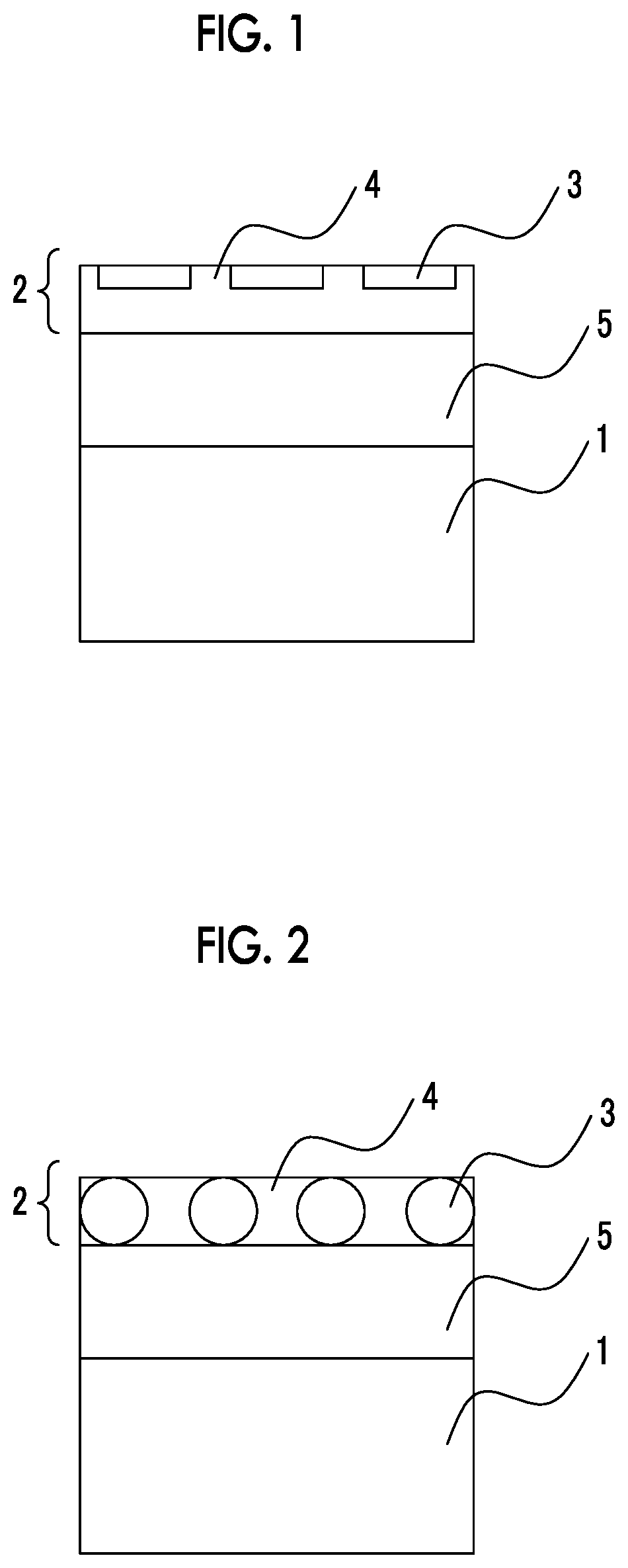
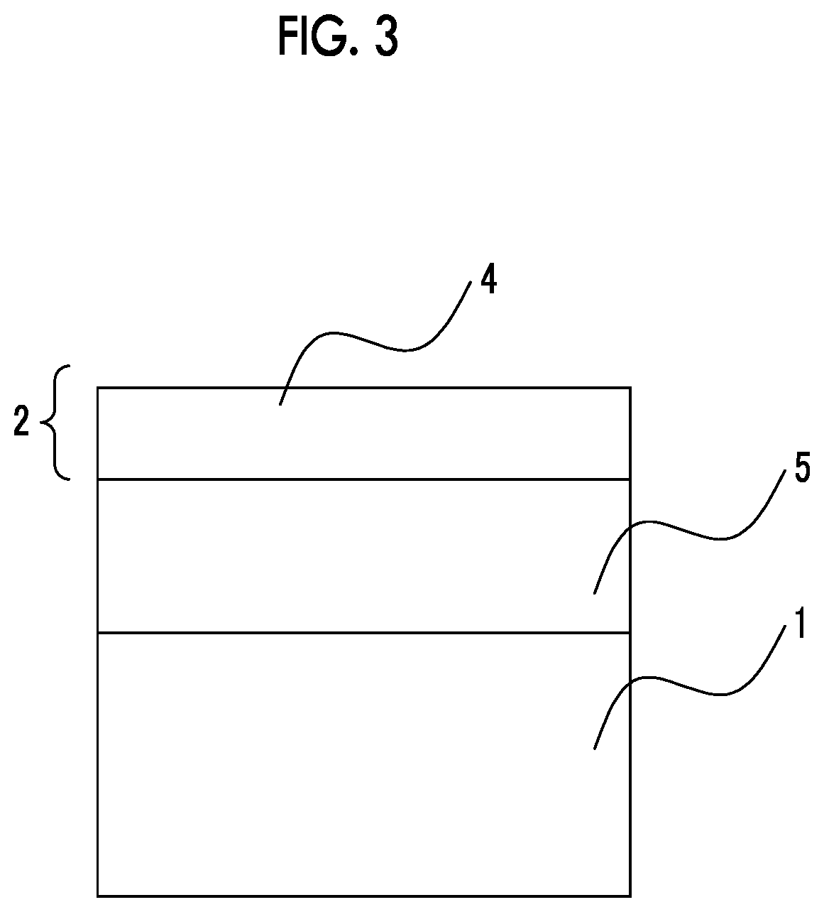
Transparent film, polarizing plate, and image displaying device
a technology of transparent film and polarizing plate, which is applied in the direction of polarizing elements, identification means, instruments, etc., can solve the problems of low flexibility in the related art, unsuitable for the protection of the surface of flexible display, and heavy and easily broken, and achieve excellent pencil hardness, excellent scratch resistance, and excellent resistance to repetitive bending
- Summary
- Abstract
- Description
- Claims
- Application Information
AI Technical Summary
Benefits of technology
Problems solved by technology
Method used
Image

Examples
example 1
[0346][Producing Base Material]
[0347](Production of Base Material Film S-1)
[0348]A methacrylic resin having a weight-average molecular weight of 1,300,000 and a methyl methacrylate (MMA) ratio of 100% was synthesized by the following method. 300 g of ion exchanged water and 0.6 g of polyvinyl alcohol (degree of saponification: 80%, degree of polymerization 1,700) were added to a 1 L three-necked flask provided with a mechanical stirrer, a thermometer, and a cooling pipe and stirred to completely dissolve the polyvinyl alcohol, and 100 g of methyl methacrylate and 0.15 g of benzoyl peroxide were added and reacted at 85° C. for six hours. The obtained suspension was filtered through a nylon filter cloth, washed with water, and the filtrate was dried overnight at 50° C. to obtain the desired methacrylic resin in a bead shape (92.0 g).
[0349]100 parts by mass of the above methacrylic resin (polymethyl methacrylate (PMMA) having a molecular weight of 1,300,000), 50 parts by mass of rubber...
example 2
[0490][Producing Coating Liquid]
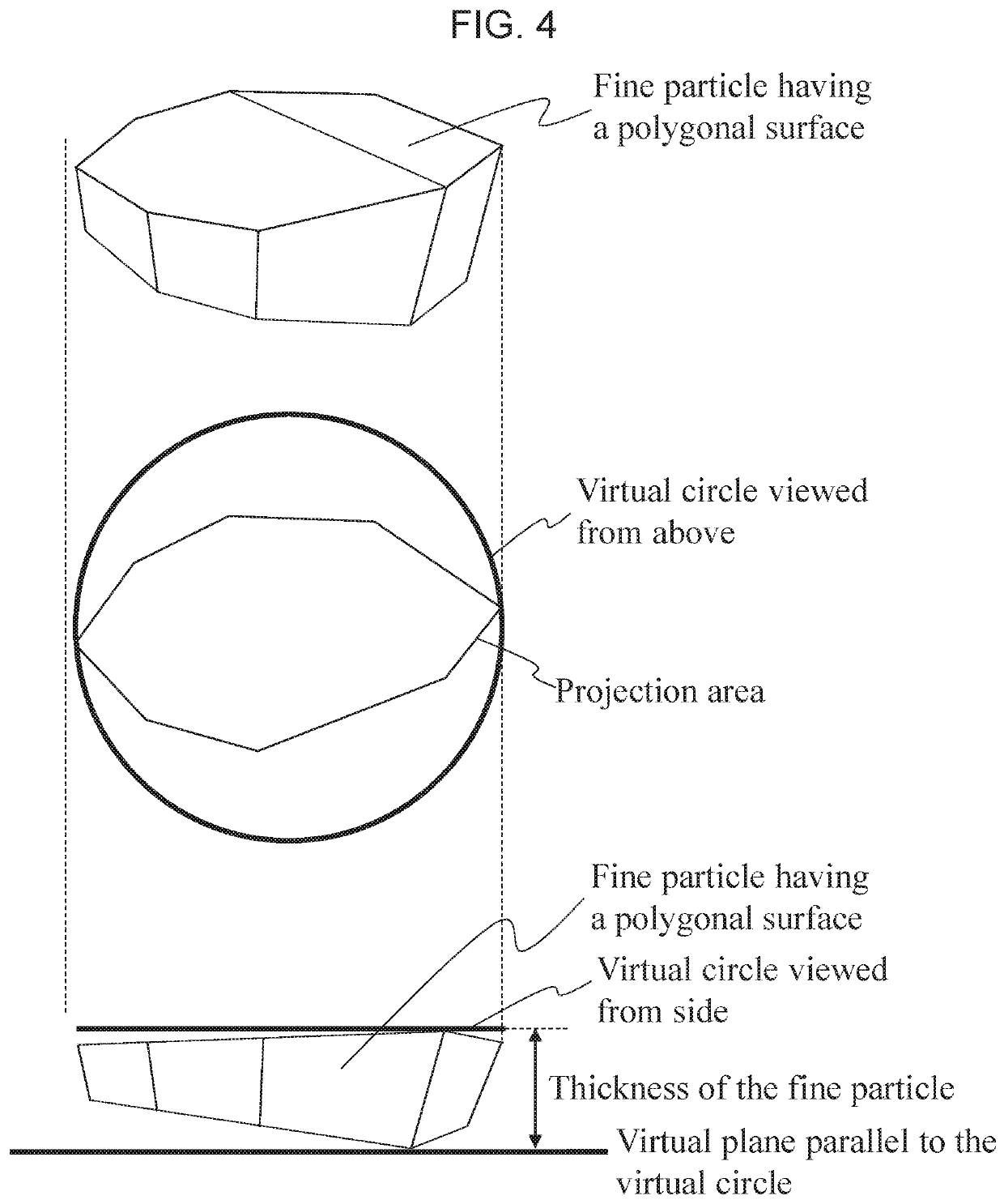
[0491](Synthesizing Silica Particles p-1)
[0492]67.54 kg of methyl alcohol and 26.33 kg of 28 mass % ammonia water (water and catalyst) were introduced to a reactor having a volume of 200 L provided with a stirrer, a dropping device, and a thermometer, and the liquid temperature was adjusted to 33° C. Meanwhile, a solution obtained by dissolving 12.70 kg of tetramethoxysilane in 5.59 kg of methyl alcohol was introduced to the dropping device. While the liquid temperature in the reactor was maintained at 33° C., the above solution was added dropwise from the dropping device over one hour. After completion of the dropwise addition, stirring was continued for one hour while the temperature were maintained at the above temperature, such that hydrolysis and condensation of tetramethoxysilane were performed and a dispersion liquid containing the silica particle precursor was obtained. This dispersion liquid was air-dried under the conditions of a heating tub...
PUM
| Property | Measurement | Unit |
|---|---|---|
| thickness | aaaaa | aaaaa |
| particle size | aaaaa | aaaaa |
| transparent | aaaaa | aaaaa |
Abstract
Description
Claims
Application Information