
Wheel hub assembly for a vehicle wheel and pole ring of an ABS sensor

a technology of abs sensor and wheel hub, which is applied in the direction of road vehicles, steering parts, off-road vehicles, etc., can solve the problems of described corrosion problems, abs sensor signal accuracy, and rust formation

Active Publication Date: 2020-03-17
BPW BERGISCHE ACHSEN KOMMANDITGES
View PDF12 Cites 2 Cited by
  • Summary
  • Abstract
  • Description
  • Claims
  • Application Information

AI Technical Summary

Benefits of technology

The patent text describes a solution that eliminates or reduces contamination problems caused by automotive operation in the region behind the pole ring, which prevents corrosion issues and other damage. The solution involves starting with the pole ring and using technical measures to create a barrier that prevents the penetration of coarse particles of dirt and fine particles of water. This barrier also allows for the escape of dirty water or small particles that may have entered the region behind the pole ring. Overall, the solution prevents damage to the wheel hub and other components, resulting in a safer and more reliable automobile.

Problems solved by technology

As a consequence, and depending on the materials being used, the formation of rust may occur there in the course of time.
This dirt—above all, coarse dirt—may also result in the described corrosion problems in the course of time.
The consequences may be an inseparable sticking of the pole ring to the hub, or an inadequate true running of the pole ring, which once again has consequences for the accuracy of the ABS sensor signal.

Method used


Image

  • Wheel hub assembly for a vehicle wheel and pole ring of an ABS sensor
  • Wheel hub assembly for a vehicle wheel and pole ring of an ABS sensor
  • Wheel hub assembly for a vehicle wheel and pole ring of an ABS sensor

Examples


Embodiment Construction

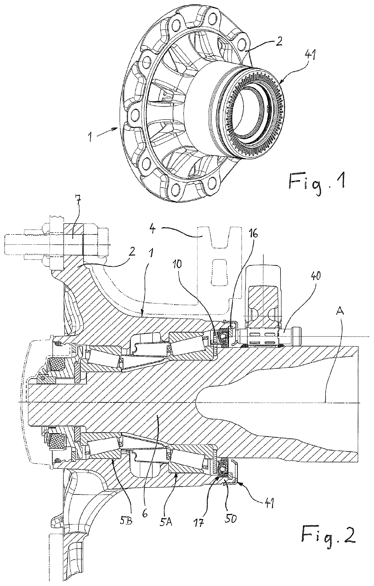
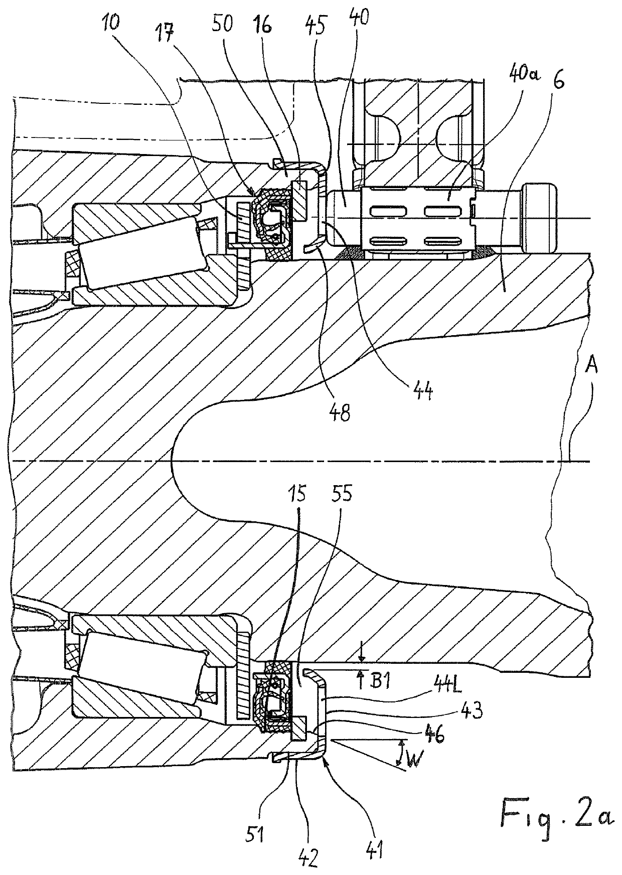
[0028]FIG. 1 shows a wheel-hub unit which in the mounted state is arranged on a steering knuckle 6 (FIG. 3) so as to be capable of rotating. Two such steering knuckles 6 are preferentially located at the ends of an extended axle beam reaching from one side of the vehicle to the other. A brake disk 4 on one side, and the vehicle on the opposite side, may have been attached to an outer flange 2 of the wheel hub 1 by means of wheel bolts 7. For this purpose, attachments with bores for passing the wheel bolts 7 through are located in the flange 2 of the wheel hub 1. Such an attachment and bearing assembly of a wheel is suitable, above all, for non-driven vehicle axles—for example, revolving axles of truck trailers.

[0029]According to FIG. 3, the axle element 6 is designed as a steering knuckle tapering toward the outside of the vehicle, on which bearing seats for an inner roller bearing 5A and an outer roller bearing 5B of a roller bearing assembly are formed. On the roller bearing assem...


PUM


Abstract

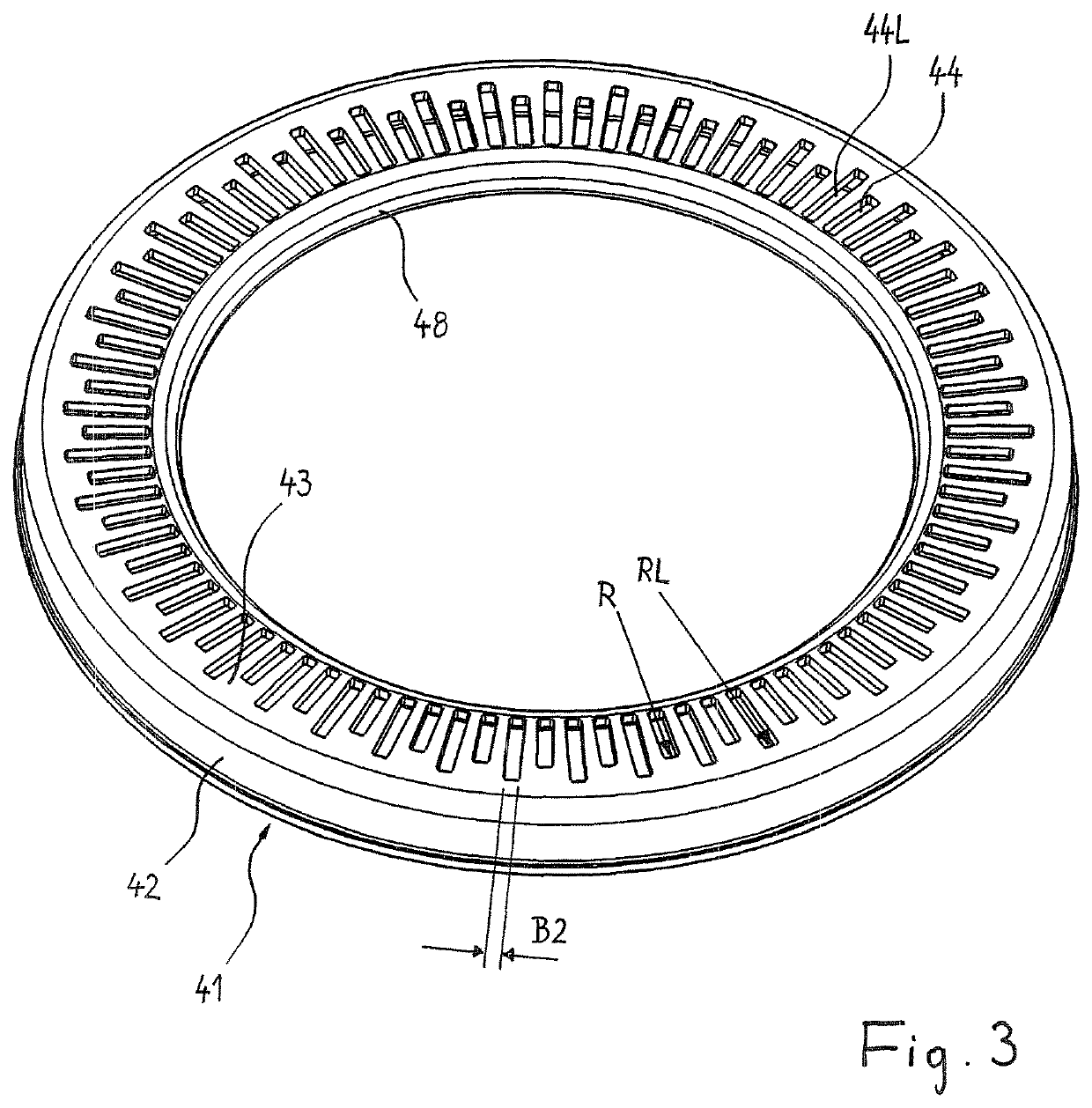
In order to provide solutions for soiling problems and corrosion problems in the area between a pole ring (41) and the hub interior, arranged behind it, of a wheel hub assembly having a wheel hub (1) which ends inside the vehicle in a hub section (50) whose internal circumference (15) defines an opening (55) for the central passage of the stub axle (6) and on which a fastening device (42) of a pole ring (41) of an ABS sensor is mounted, wherein a pulse generator section (43) which is embodied in one piece with the fastening section (42) is a component of the pole ring (41), which pulse generator section (43) extends from the fastening section (42) to the wheel hub axis (A) and is provided with openings (44, 44L) distributed uniformly in the circumferential direction; in a first embodiment the pole ring (41) extends with its pulse generator section (43) towards the wheel hub axis (A) to such an extent that the opening (55) between the wheel hub (1) and stub axle (6) is for the most part covered towards the interior of the hub. In a second embodiment, at least some of the openings or slots have an extent (RL) towards the outside which is greater than the extent (R) which is necessary for sensing. Furthermore, it is proposed with respect to the pole ring (41) that some of the openings (44L) or slots have an extent (RL) towards the outside which is greater than the extent (R) of other openings (44) or slots.

Description

BACKGROUND OF THE INVENTION[0001]The invention relates firstly to a wheel-hub assembly for a vehicle wheel, with a wheel hub which is arranged so as to be capable of rotating on a torsion-resistant steering knuckle via a hub bearing assembly and which terminates inside the vehicle in a hub neck, the inner periphery of which defines an opening for the central passage of the steering knuckle, and on which an attachment portion of a pole ring of an ABS sensor is mounted, wherein a component of the pole ring is a pulse-generator portion integrally formed with the attachment portion, which extends, starting from the attachment portion, toward the wheel-hub axis. The invention further relates to a wheel-hub assembly as described, which is provided with openings, preferentially slots, uniformly distributed in the peripheral direction.[0002]The invention relates further to a pole ring for an ABS sensor for sensing the rotation of a vehicle wheel, with an attachment portion for mounting the ...

Claims


Application Information

Patent Timeline
Patent Type & Authority Patents(United States)
IPC IPC(8): B60B27/00B60B27/02B62D7/18
CPCB60B27/0068B60B27/02B60B27/0073B60B2900/5114B60B2310/206B62D7/18B60Y2200/20B60B2900/211B60B2900/5112B60B2310/228B60B2310/211B60Y2200/10B60B27/00F16C33/72
Inventor ILIEV, ROSSENSIEBEL, REINERWASSERFUHR, WILFRIED
Owner BPW BERGISCHE ACHSEN KOMMANDITGES
Learn More