Shadow removing method for color image and application

a color image and application technology, applied in image enhancement, image analysis, instruments, etc., can solve the problem of another big problem, the difference between illumination and color image, and achieve the effect of low complexity, poor discrimination and high accuracy

Active Publication Date: 2020-03-17
PEKING UNIV SHENZHEN GRADUATE SCHOOL
View PDF9 Cites 0 Cited by
  • Summary
  • Abstract
  • Description
  • Claims
  • Application Information

AI Technical Summary

Benefits of technology

[0034]Compared with the prior art, the invention has the following beneficial effects:
[0035]Compared with the three existing technologies summarized in the background art (anti-shadow feature extractor, shadow-free feature extractor, and shadow detection and removal method), the method combines the advantages of low complexity (determining the processing speed) and high accuracy. For some cases of strong shadows, neither the anti-shadow feature extractor nor the shadow-free feature extractor can work well. Moreover, feature images extracted by the anti-shadow feature extractor and the shadow-free feature extractor have poor discrimination, which is not conducive to the subsequent image processing and analysis work.
[0036]In contrast, the shadow removing method provided by the invention has good discrimination and facilitates subsequent processing such as image segmentation. The third technology, shadow detection and removal, has the defects of high complexity and slow processing speed, while the method provided by the invention realizes an accurate shadow removal effect under the condition of low complexity and can cope with occasions requiring high real-time performance. Therefore, the method of the invention can remove shadows existing in a color image and is applied to various machine vision fields as a pre-processing step. By adopting the shadow removing method provided by the invention firstly for pre-processing, and then using a corresponding processing method, the robustness of the shadow removing method to shadow interference can be improved, and better performance can be achieved.

Problems solved by technology

In the case of image matching, illumination difference is another big problem in image matching.

Method used


Image

  • Shadow removing method for color image and application
  • Shadow removing method for color image and application

Examples


example 1

[0059]In the example of the invention, based on the design framework of a shadow-free feature extractor, a shadow-free feature extractor suitable for road surface detection is provided, which comprises the following steps:

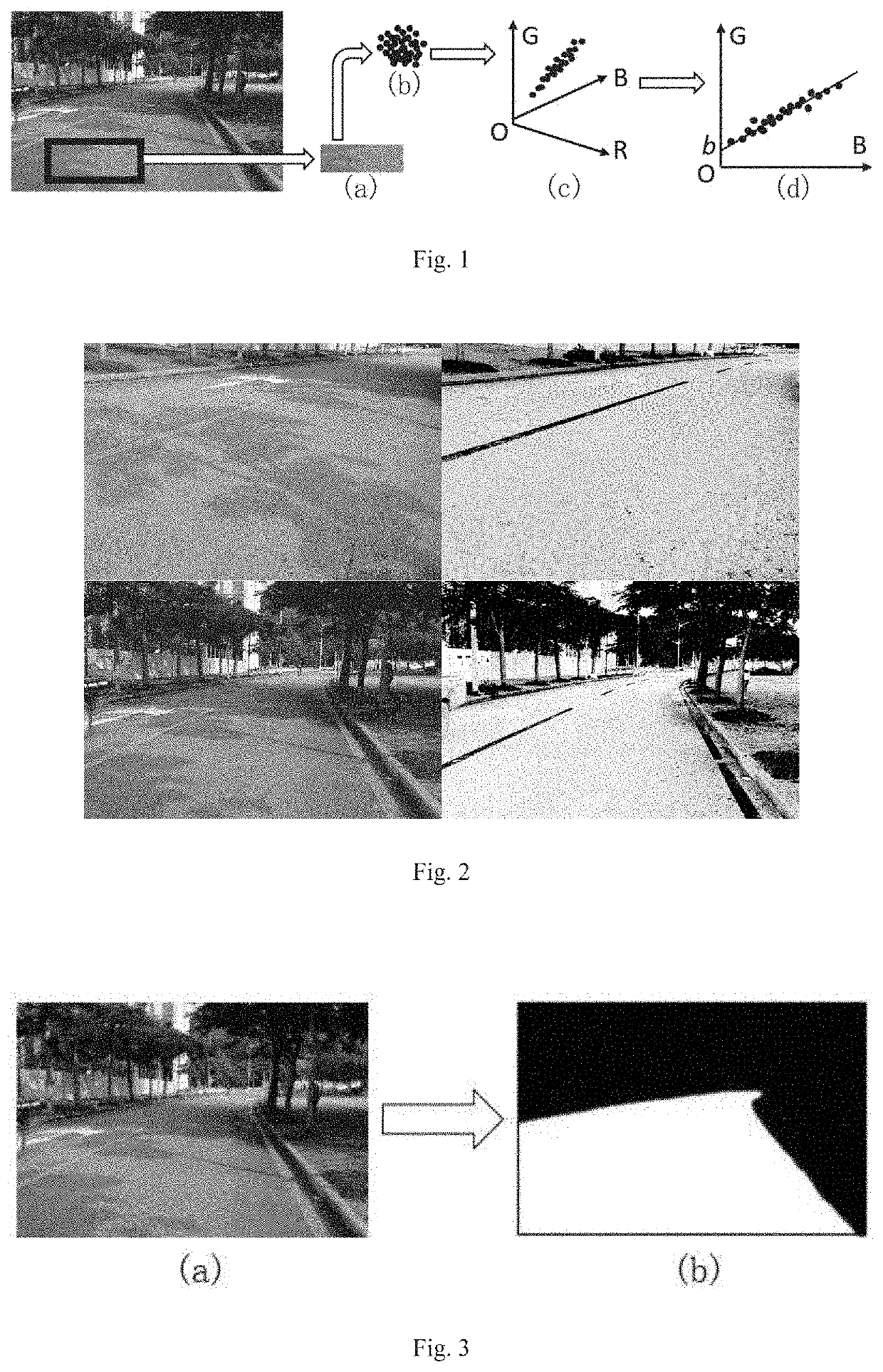
[0060]Offline camera calibration: An image of an application scene is calibrated, i.e. an object region of interest is manually marked. Calibration can be accomplished using interactive software. For road surface detection, the region we are interested in is a road surface. After opening a shadowy image and marking part of the road surface region, as shown in FIG. 1 (a), the interactive software will draw image pixels inside the region, as shown in FIG. 1 (b), to RGB space as shown in FIG. 1 (c), and then conduct projection to GB space. The distribution of pixel point clouds can be fitted by a straight line equation, the intercept b of the straight line on the G axis obtained through data fitting by the software is the required camera parameter, as shown in FIG. 1 ...

example 2

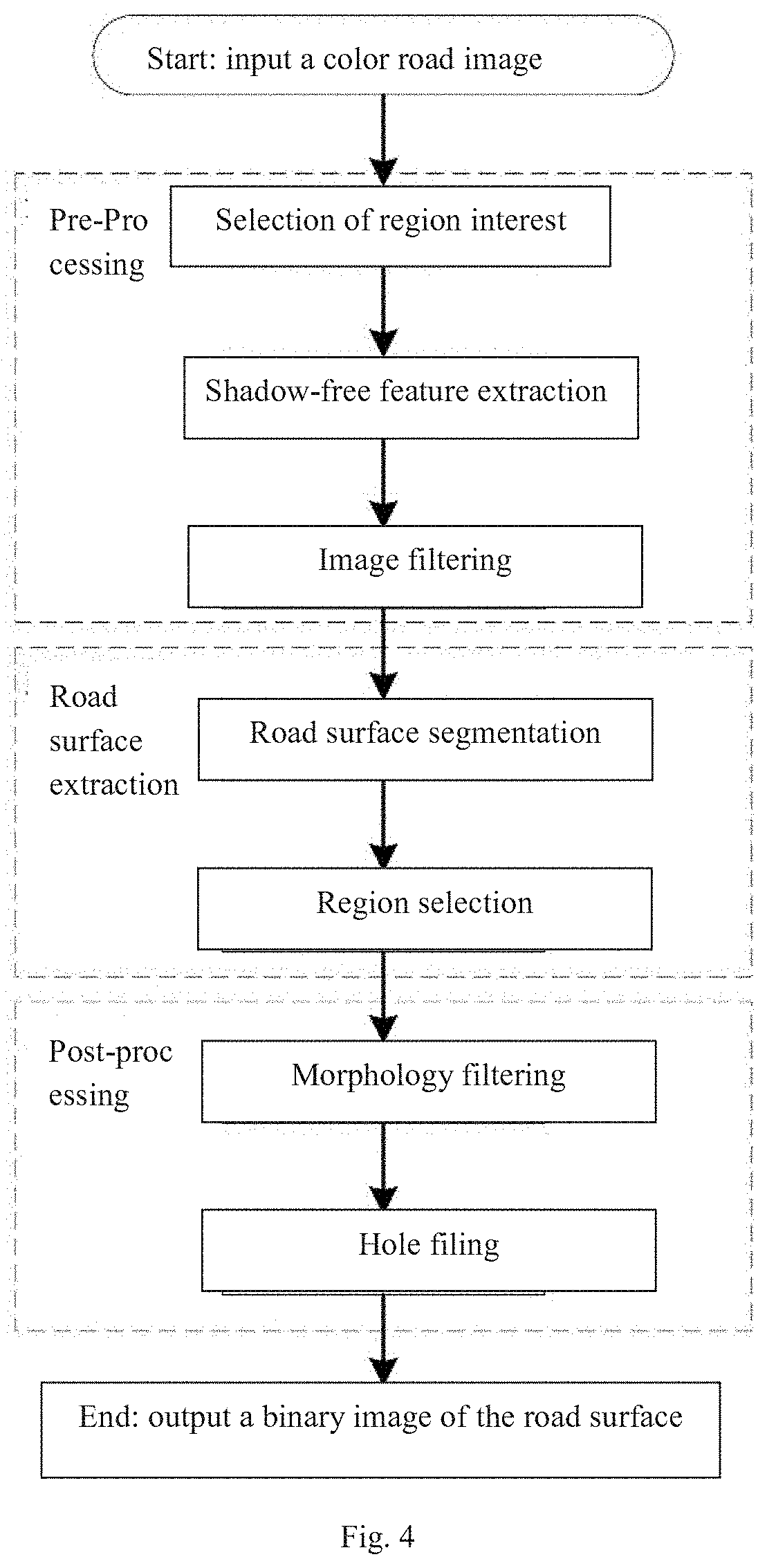
[0064]In the example of the invention, a road surface detection method is provided. The road detection method processes a road image from the view of a driver and detects the region where the road surface is located, as shown in FIG. 3. The frame of the road surface detection method is shown in FIG. 4 and specifically comprises the following steps:

[0065]Selection of region of interest (ROI): The step limits the subsequent processing steps to one sub-region to improve the system efficiency. Processing irrelevant regions not only wastes time, but also may introduce noise to affect the performance of a system. Therefore, the first step is to define which image regions are useless and which regions are useful for implementation and application. Regions useful for subsequent processing are called regions of interest. In addition, from a simple point of view, rectangular regions of interest are generally selected and divided according to a rectangular ROI window to directly obtain a sub-i...


PUM


Abstract

Disclosed are a shadow removing method for an image and an application. The shadow removing method comprises a shadow-free feature analysis process, a shadow-free transformation parameter acquisition process and a shadow-free feature imaging process. The application is for road surface detection, a detection method comprising: firstly, using a shadow-free feature extraction method to select a region of interest and extract a feature; next, performing image filtering, segmentation and road surface region selection; lastly, performing image morphology filtering and hole filling. The method may remove shadows in color images, thus serving as a pre-processing step applied in various machine vision fields, and the application in road surface detection may solve the problem of detecting a road surface in dark shadows. The method has the advantages of having low complexity, high processing speed and high accuracy.

Description

CROSS-REFERENCE TO RELATED PATENT APPLICATIONS[0001]The present application is a U.S. national stage application under 35 U.S.C. § 371 of PCT Application No. PCT / CN2016 / 109612, filed Dec. 13, 2016, which claims priority to Chinese Patent Application No. 201610621447X, filed Aug. 1, 2016. The disclosures of the aforementioned priority applications are incorporated herein by reference in their entireties.TECHNICAL FIELD[0002]The invention relates to the field of machine vision, in particular to a shadow removing method for a color image and an application in road surface region detection based on the method.BACKGROUND ART[0003]Shadows in images have influence on machine vision algorithms for edge extraction and image matching. A color image is composed of three grayscale component images of RGB. Since the grayscale images of the three components are quite similar, the machine vision algorithms usually convert them into one grayscale component for processing. Since all of the three gra...

Claims


Application Information

Patent Timeline
Patent Type & Authority Patents(United States)
IPC IPC(8): G06K9/00G06T7/11G06T7/90G06K9/44G06T5/00G06V10/25G06V10/56G06V10/60
CPCG06T7/11G06K9/00798G06T5/002G06T7/90G06K9/44G06T2207/10024G06T2207/30256G06T5/008G06V20/588G06V10/25G06V10/267G06V10/60G06V10/56
Inventor LI, GEYING, ZHENQIANG
Owner PEKING UNIV SHENZHEN GRADUATE SCHOOL
Why Eureka
Try Eureka