Shielded high density jack

a high-density shielding and jack technology, applied in the direction of coupling devices, coupling devices, coupling bases/cases, etc., can solve the problems of reducing shield performance, potential degradation of cable performance and impedance changes, and additional shielding failures, etc., to achieve high performance

Active Publication Date: 2020-03-17
LEGRAND DPC LLC
View PDF24 Cites 9 Cited by
  • Summary
  • Abstract
  • Description
  • Claims
  • Application Information

AI Technical Summary

Benefits of technology

[0007]The present disclosure provides advantageous electrical connector assemblies or jack assemblies / housings, and improved methods / systems for shielding the same. More particularly, the present disclosure provides improved shielding techniques / assembly for high performance and high density shielded modular electrical connector assemblies for communication systems (e.g., voice / data / video systems).
[0008]In exemplary embodiments, the present disclosure provides an advantageous shielding assembly or electrical connector assembly that is configured and adapted to minimize the connection path and provide a more direct connection to plug / cable and / or foil / cable ground wire and mounting panel. More particularly, the advantageous shielding assembly provides direct connection through a modular voice / data / video connector. As such, the present disclosure provides for a more direct shielding connection that reduces the potential for a substantial degradation of performance over time.

Problems solved by technology

The multiple connections may result in additional shielding failures and over time increased contact resistance that may reduce shield performance.
Furthermore, by separating the shielded incoming cable wire from the foil, the potential for degradation of the cable performance and impedance changes may result.
Additionally, to maintain contact to the cable shield during flex, conventional practice can utilize multiple parts / cable clamps / plastic ties, which may degrade performance over time (e.g., due to temperature cycling and increased contact resistance).

Method used


Image

  • Shielded high density jack
  • Shielded high density jack
  • Shielded high density jack

Examples


Embodiment Construction

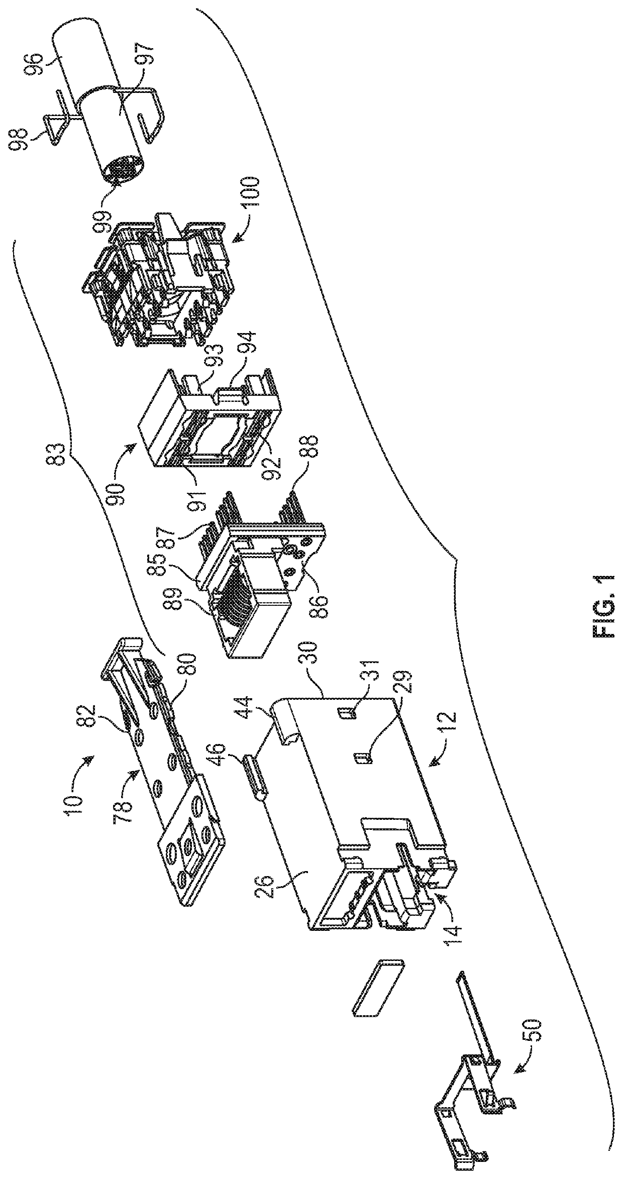
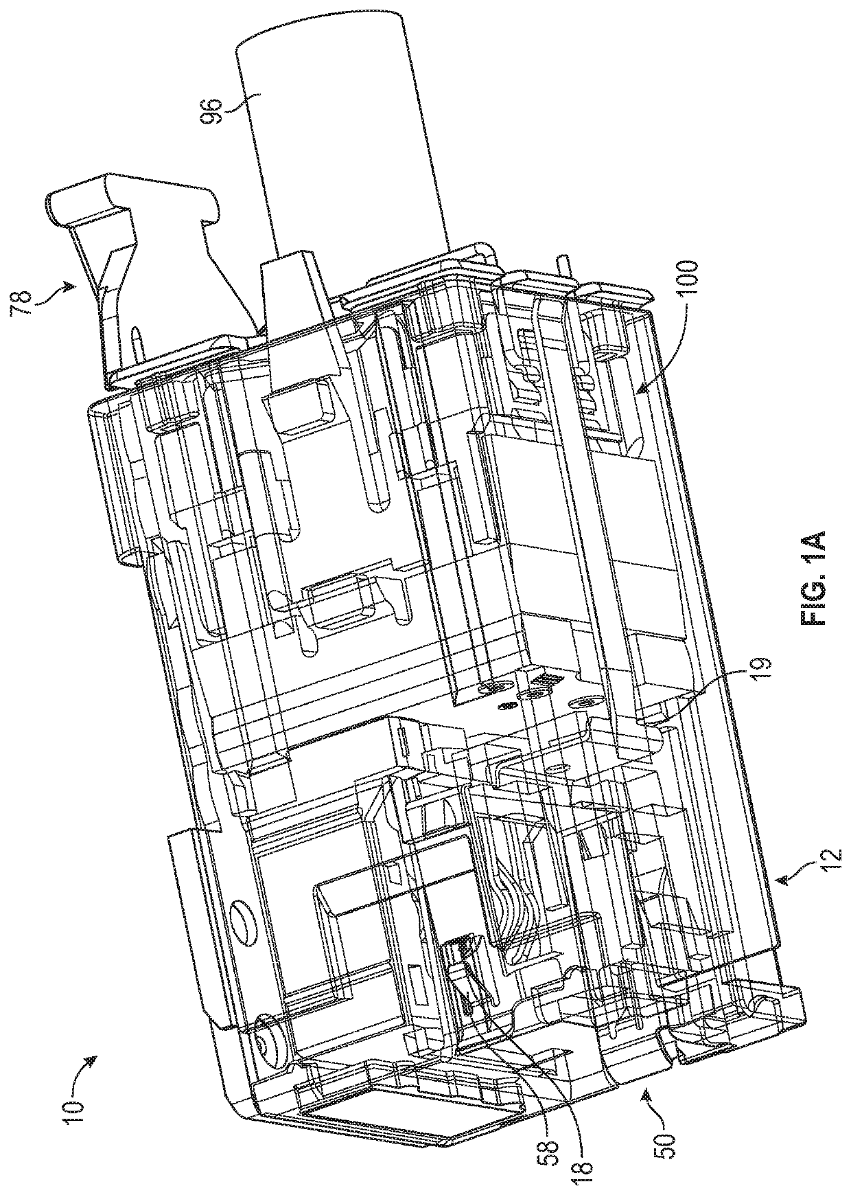
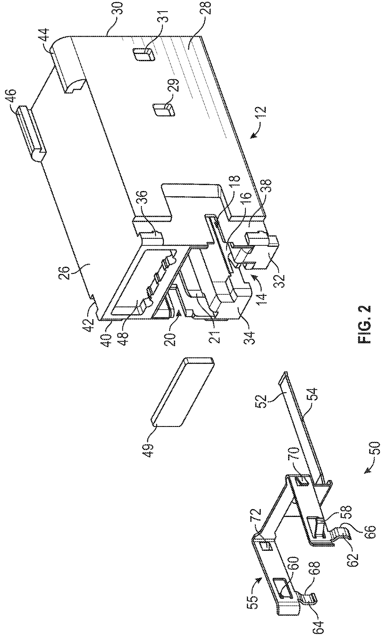
[0031]The exemplary embodiments disclosed herein are illustrative of advantageous shielding assemblies (e.g., modular electrical connector shielding assemblies), and systems of the present disclosure and methods / techniques thereof. It should be understood, however, that the disclosed embodiments are merely exemplary of the present disclosure, which may be embodied in various forms. Therefore, details disclosed herein with reference to exemplary assemblies / fabrication methods and associated processes / techniques of assembly and use are not to be interpreted as limiting, but merely as the basis for teaching one skilled in the art how to make and use the advantageous assemblies / systems (e.g., modular electrical connector shielding assemblies) and / or alternative assemblies of the present disclosure.

[0032]The present disclosure provides improved shielding assemblies (e.g., modular connector shielding assemblies), and advantageous methods / systems for using the same. More particularly, the ...


PUM


Abstract

Advantageous electrical connector assemblies or jack assemblies / housings for use in communication systems are provided. The present disclosure provides systems / methods for the design and use of high density shielded modular electrical connectors that include improved shielding techniques. The present disclosure provides for a direct shielded connection throughout a shielded modular electrical connector. The shielded modular electrical connector provides for a single continuous contact with a shielded cable. The electrical connector assemblies are configured to facilitate a direct shielding connection that minimizes the connection path and provides a more direct connection to plug / cable and / or foil / cable ground wire and mounting panel. The shielding assembly includes a modular voice / data / video connector that further includes a modular plug contact and a wrap-around shield contact. The modular plug contact can include both cable shield contacts and plug contacts. The wrap-around shield contact can include a continuously formed material that captures a cable shield.

Description

CROSS-REFERENCE TO RELATED APPLICATIONS[0001]This application claims the benefit of U.S. Provisional Applications entitled “Shielded High Density Jack,” which was filed on Nov. 21, 2017, and assigned Ser. No. 62 / 589,320, the contents of which are herein incorporated by reference in their entirety.FIELD OF THE DISCLOSURE[0002]The present disclosure generally relates to electrical connector assemblies or jack assemblies / housings for use in communication systems (e.g., voice / data / video communication systems) and, more particularly, to high performance and high density shielded modular electrical connector assemblies that include improved shielding techniques.BACKGROUND OF THE DISCLOSURE[0003]In general, devices for interfacing with high frequency data transfer media are known. See, e.g., U.S. Pat. Nos. 8,333,607; 7,857,663 and 7,758,383, the entire contents of each being hereby incorporated by reference in their entireties.[0004]Traditionally, shielding techniques for voice / data / video ...

Claims


Application Information

Patent Timeline
Patent Type & Authority Patents(United States)
IPC IPC(8): H01R13/648H01R13/502H01R13/6582H01R13/6596H01R13/6593H01R13/506H01R13/46H01R24/64H01R12/71H01R4/2425H01R13/518H01R13/66
CPCH01R13/6593H01R13/6596H01R13/6582H01R13/502H01R13/6658H01R13/506H01R13/518H01R13/465H01R4/2425H01R12/716H01R24/64
Inventor CUPPLES, KENNETH ALANPETRUSKEVICIUS, DYLAN ROBERT
Owner LEGRAND DPC LLC
Why Eureka
Try Eureka