Microphone device
a microphone and microphone technology, applied in the direction of mouthpiece/microphone attachment, current supply arrangement, power management, etc., can solve the problems of poor weight-feeling of the wireless microphone housing, difficult to handle the wireless microphone, and impair the design quality of the microphone, so as to improve the convenience of the user and improve the handling
- Summary
- Abstract
- Description
- Claims
- Application Information
AI Technical Summary
Benefits of technology
Problems solved by technology
Method used
Image

Examples
embodiment 1
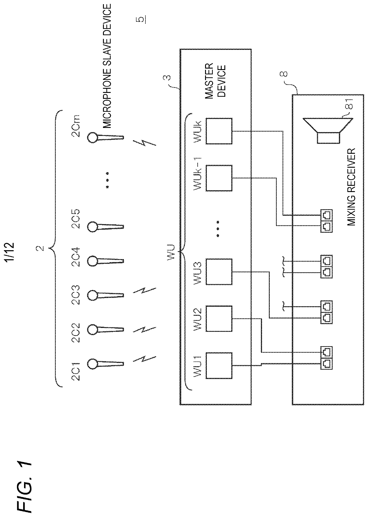
[0022]FIG. 1 is a diagram schematically illustrating a system configuration example of a wireless microphone system 5 according to Embodiment 1. The wireless microphone system 5 is configured to include a plurality (for example, m) of microphone slave devices 2, a master device 3 as an example of a receiving device, and a mixing and receiving device 8. Here, m is an integer equal to or larger than 2. In the following description, in a case where a plurality of microphone slave devices 2C1, 2C2, . . . , and 2Cm are not particularly distinguished from one another, each of the plurality of microphone slave devices 2C1, 2C2, . . . , and 2Cm is referred to as the microphone slave device 2.
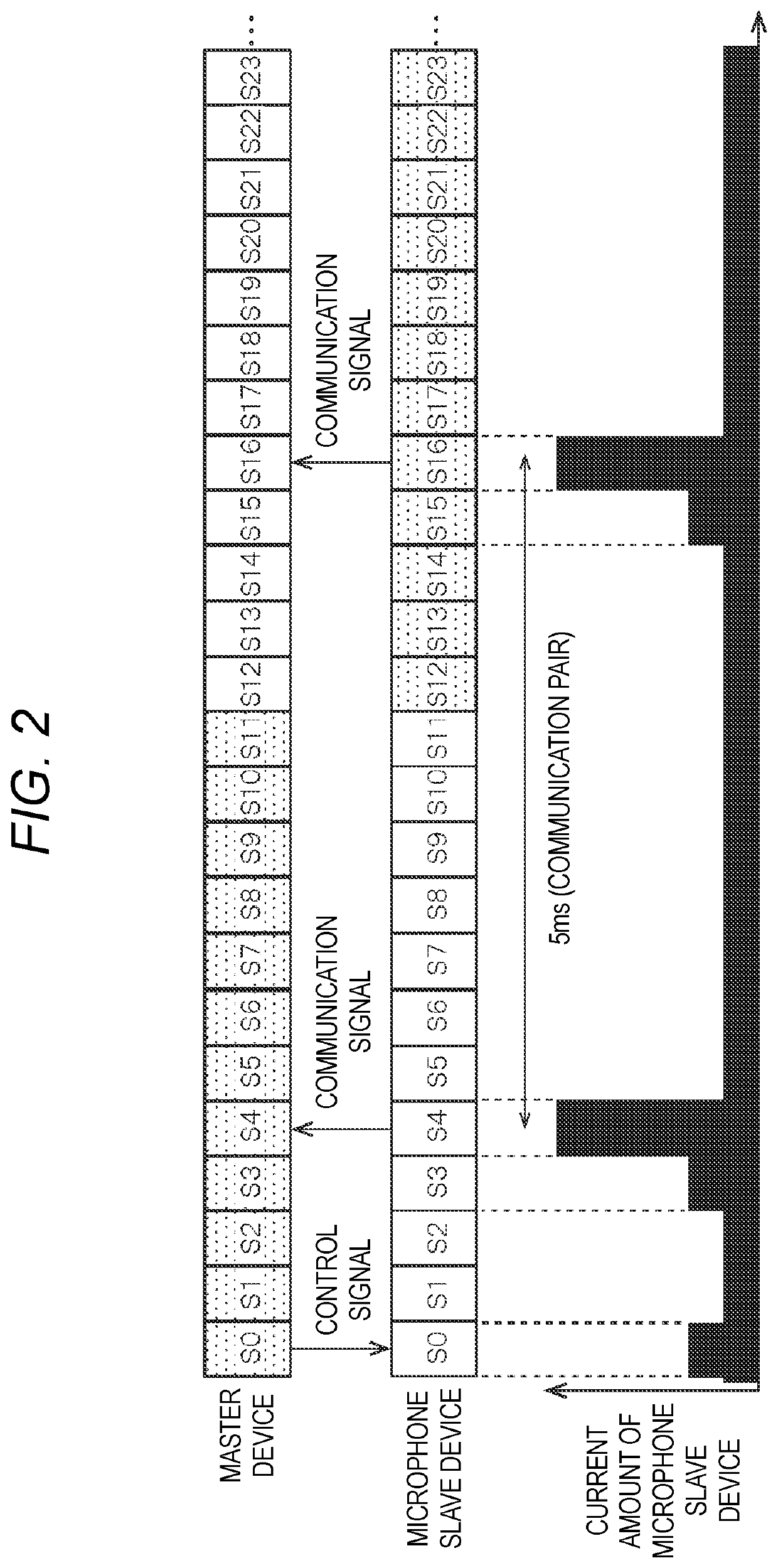
[0023]A wireless signal (for example, an audio signal or a control signal) is transmitted and received between the microphone slave device 2 and the master device 3 through a wireless line according to a communication standard (for example, a time division multiplex communication method) of a time divis...
embodiment 2
[0078]In the power supply unit 50 of the microphone slave device 2 according to Embodiment 1, the inrush current preventing circuit 51 suppresses the inrush current flowing through the large capacity capacitor 52. For the power supply unit 50 of the microphone slave device 2 according to Embodiment 2, an example in which the current as the inrush current is suppressed to be a constant current will be described.
[0079]The power supply unit 50 of the microphone slave device 2 according to Embodiment 2 has the same configuration as the power supply unit 50 of the microphone slave device 2 according to Embodiment 1 except for a suppression circuit 60A, so the same as in Embodiment 1 is denoted by the same reference numeral, and description thereof will be simplified or omitted.
[0080]FIG. 7 is a diagram illustrating a configuration example of the suppression circuit 60A according to Embodiment 2. The suppression circuit 60A is configured to include a current suppression circuit 71, an inr...
embodiment 3
[0092]In Embodiment 1, the inrush current preventing circuit 51 suppresses the inrush current flowing through the large capacity capacitor 52. In Embodiment 2, the current flowing as the inrush current is suppressed to be a predetermined constant current and in a case where the DCDC up-converter 53 has a low operation voltage as compared with the others, the voltage monitor circuit 73 maintains the off-signal (as described above) but the DCDC up-converter 53 can operate. Therefore, there is a deviation at the timing when the DCDC up-converters 53, 54, 55, and 56 are activated.
[0093]In Embodiment 3, an example, in which the microphone slave device 2 is more stably activated by suppressing the amount of current of the inrush current at the time of providing the battery 16 in the same manner as Embodiment 2 and further selecting timings when various type of the DCDC up-converters 53, 54, 55, and 56 provided in the microphone slave device 2 are activated, will be described.
[0094]The pow...
PUM
 Abstract
Description
Claims
Application Information
 - R&D
- Intellectual Property
- Life Sciences
- Materials
- Tech Scout
- Unparalleled Data Quality
- Higher Quality Content
- 60% Fewer Hallucinations
Browse by: Latest US Patents, China's latest patents, Technical Efficacy Thesaurus, Application Domain, Technology Topic, Popular Technical Reports.
© 2025 PatSnap. All rights reserved.Legal|Privacy policy|Modern Slavery Act Transparency Statement|Sitemap|About US| Contact US: help@patsnap.com