
Fault mitigation for electrical actuator using regulated voltage control

a technology of regulated voltage control and fault mitigation, which is applied in the direction of electric control, safety/protection circuit, machines/engines, etc., can solve the problems of actuators that cease to function at a sufficient rate, actuator function may degrade over time, etc., and achieve the effect of reducing the fault condition

Active Publication Date: 2020-04-07
GM GLOBAL TECH OPERATIONS LLC
View PDF4 Cites 1 Cited by
  • Summary
  • Abstract
  • Description
  • Claims
  • Application Information

AI Technical Summary

Benefits of technology

[0002]Electrically controlled actuators are used in many systems of an automobile vehicle, including but not limited to fuel pumps, camshafts, and the like. Many known actuators operate with electrical motors controlled using a pulse width modulation voltage. Actuator function may degrade over time due to various conditions, including wear, temperature extremes including overheating, and friction. As actuators degrade, known control systems which sense a state of health (SOH) of the actuators may attempt to compensate for reduced actuator output in several ways. One such way is to increase the actuator output by increasing its input to a predetermined maximum amount, for example by increasing a fuel pump output pressure by applying a maximum pulse width modulated (PWM) duty cycle of the pump. A further way is to decrease the duty cycle of the pump by reducing or optimizing pump operation when possible to extend pump life.
[0005]According to several aspects, a method for mitigating an electrical actuator fault in a system containing multiple actuators includes: applying multiple predetermined conditions to each of multiple actuators in a vehicle system to identify when at least one of the multiple actuators is in a faulted condition; and increasing an input voltage to all of the actuators to increase an output of the at least one of the multiple actuators in the faulted condition to mitigate the faulted condition.

Problems solved by technology

Actuator function may degrade over time due to various conditions, including wear, temperature extremes including overheating, and friction.
When degradation occurs resulting in an actuator fault, known vehicle health management (VHM) systems do not provide fault mitigation, but generally only provide a fault signal to the vehicle operator and may generate a diagnostic code for use by a maintenance technician or for remote transmission if the vehicle is equipped with a telematics unit.
This may undesirably result in a “walk home” incident, wherein an actuator ceases to function at a sufficient rate for sustaining proper operation of the engine or transmission.

Method used


Image

  • Fault mitigation for electrical actuator using regulated voltage control
  • Fault mitigation for electrical actuator using regulated voltage control
  • Fault mitigation for electrical actuator using regulated voltage control

Examples


Embodiment Construction

[0031]The following description is merely exemplary in nature and is not intended to limit the present disclosure, application, or uses.

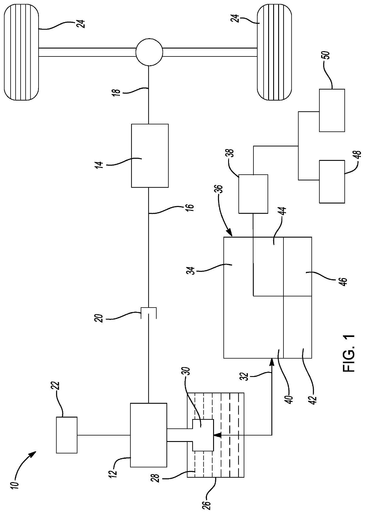
[0032]Referring to the Figures in general, wherein like reference numbers correspond to like or similar components throughout the several figures, and referring specifically to FIG. 1, a vehicle 10 includes an internal combustion engine 12 providing motive force to a transmission 14 having an input member 16 and an output member 18. The engine 12 may be selectively connected to the transmission 14 using an input clutch and damper assembly 20. The vehicle 10 may also include a DC energy storage system 22, e.g., a rechargeable battery, which may be electrically connected to provide starting current to the engine 12, or to provide power if the vehicle 10 is a hybrid electric vehicle (HEV). Output torque from the transmission 14 is ultimately transferred via the output member 18 to a set of driven wheels 24 to propel the vehicle 10.

[0033]Vehicle 10 furt...


PUM


Abstract

A method for mitigating an electrical actuator fault in a system containing multiple actuators includes: applying multiple predetermined conditions to each of multiple actuators in a vehicle system to identify when at least one of the multiple actuators is in a faulted condition; and increasing an input voltage to all of the actuators to increase an output of the at least one of the multiple actuators in the faulted condition to mitigate the faulted condition.

Description

INTRODUCTION[0001]The present disclosure relates to electrically controlled actuators used in motor vehicles.[0002]Electrically controlled actuators are used in many systems of an automobile vehicle, including but not limited to fuel pumps, camshafts, and the like. Many known actuators operate with electrical motors controlled using a pulse width modulation voltage. Actuator function may degrade over time due to various conditions, including wear, temperature extremes including overheating, and friction. As actuators degrade, known control systems which sense a state of health (SOH) of the actuators may attempt to compensate for reduced actuator output in several ways. One such way is to increase the actuator output by increasing its input to a predetermined maximum amount, for example by increasing a fuel pump output pressure by applying a maximum pulse width modulated (PWM) duty cycle of the pump. A further way is to decrease the duty cycle of the pump by reducing or optimizing pu...

Claims


Application Information

Patent Timeline
Patent Type & Authority Patents(United States)
IPC IPC(8): H02H1/06H02H9/04B60R16/03H02J7/14F02D41/22F02D29/06F02D41/30
CPCH02J7/0029H02H9/045H02H1/06H02J7/14B60R16/03F02D41/221F02D41/3082F02D29/06F02D41/20F02M37/10H02J7/005H02J7/00308Y02T10/40
Inventor HU, YAODU, XINYUSANCHEZ, JOSHUA J.KRAJEWSKI, PAUL E.
Owner GM GLOBAL TECH OPERATIONS LLC
Learn More