Rigid and flexible doctor blade holder and system comprising a cylinder and a doctor blade holder

a flexible, doctor blade technology, applied in the field of doctor blade holders, can solve the problems of easy breakage, difficult maintenance and use, and simple construction

Active Publication Date: 2020-04-28
ORADOC
View PDF19 Cites 2 Cited by
  • Summary
  • Abstract
  • Description
  • Claims
  • Application Information

AI Technical Summary

Benefits of technology

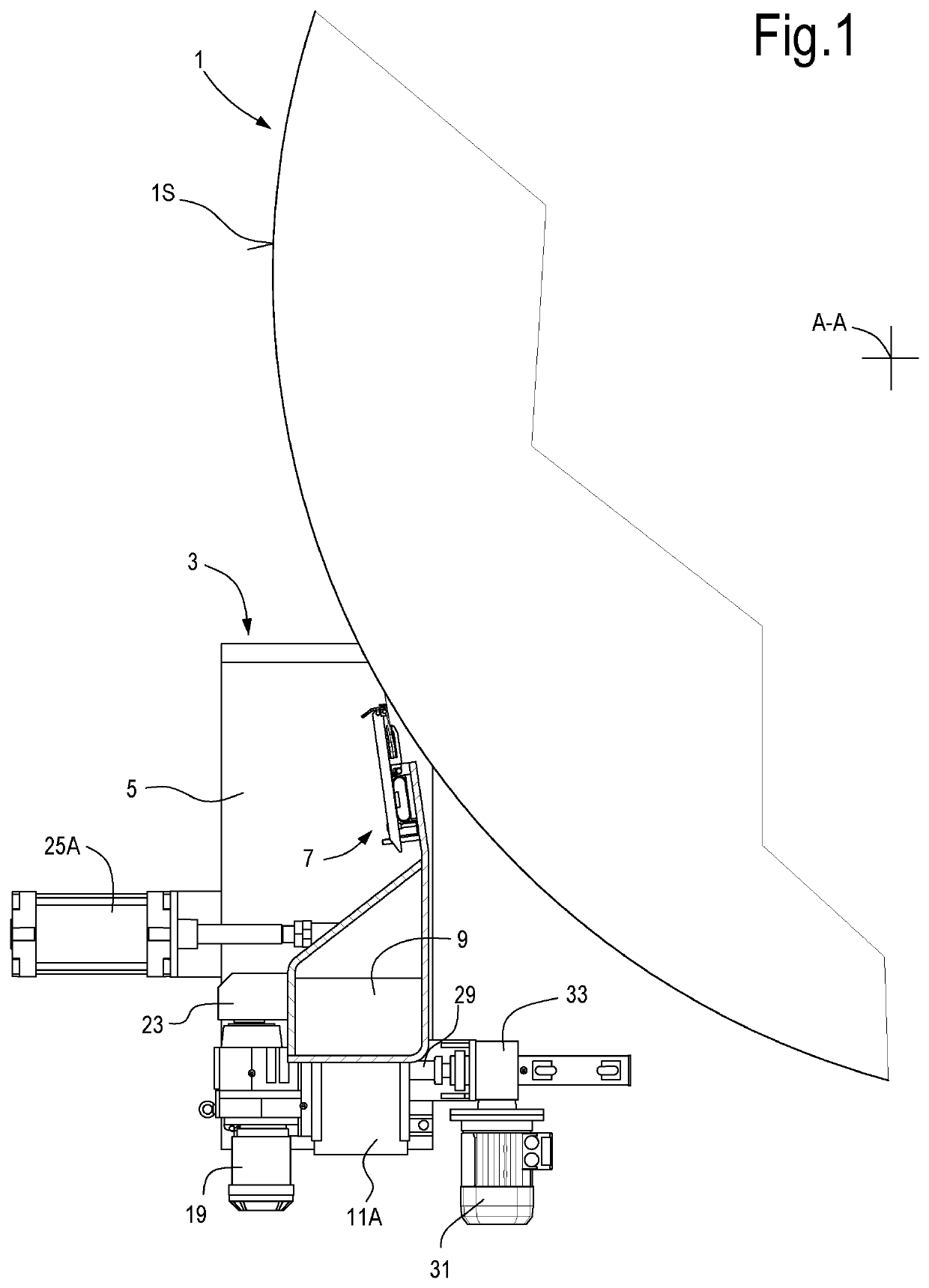
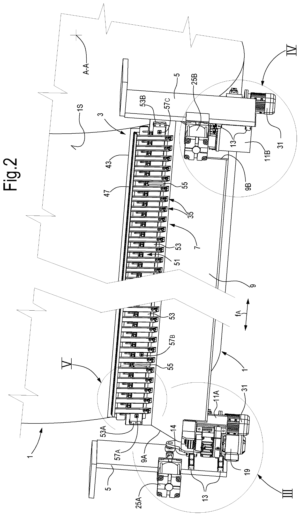
[0009]According to one aspect, disclosed herein is a doctor blade holder for a doctor blade adapted to co-act with a cylindrical surface of a rotating cylinder, comprising a plurality of fingers mounted on a beam, hinged around a rotation axis and configured to cumulatively form a housing seat for a doctor blade. The fingers are pivotable independently from one another around the rotation axis. The doctor blade holder further comprises at least one elastic thrust member, for example comprising at least one spring or a system of springs, or comprising at least one chamber that can be inflated with a pressurized fluid. The thrust member is configured and arranged to generate a thrust on the fingers to make them pivot around said rotation axis. Each finger can also comprise a locking element, to rigidly lock the finger to the beam. In this way, a doctor blade holder can be obtained that can alternatively act as a flexible doctor blade holder and as a rigid doctor blade holder of the current art, combining in the same device the advantages of the two currently known types of doctor blade holder.
[0014]In practical embodiments, the deformation of the springs is actually very slight and consequently the variations of elastic force generated by the single springs are also minimal. In this way it is possible to maintain substantially the same elastic load for all the springs fitted on a single doctor blade holder.
[0016]In substance, a doctor blade holder of this type allows the doctor blade to be optimally shaped on the profile of the cylinder exerting constant pressure and causing a deformation that can vary locally from area to area, due to the flexibility of the inflatable chamber, or other elastic thrust member, and to the fact that each finger can pivot independently from the others. After reaching the correct shape of the doctor blade, without the need to apply excessive localized pressures as is instead necessary in rigid systems, the fingers can be locked on the beam so that the doctor blade holder as a whole will operate as a normal rigid doctor blade holder.
[0018]In this way it is possible to replace each finger independently from the others, without removing a common hinge member and the whole pressure plate. Maintenance of the doctor blade holder is thus simpler and it is no longer necessary to have several spare assembled doctor blade holders for replacement in the case of breakage of one or more doctor blade holder fingers during operation.
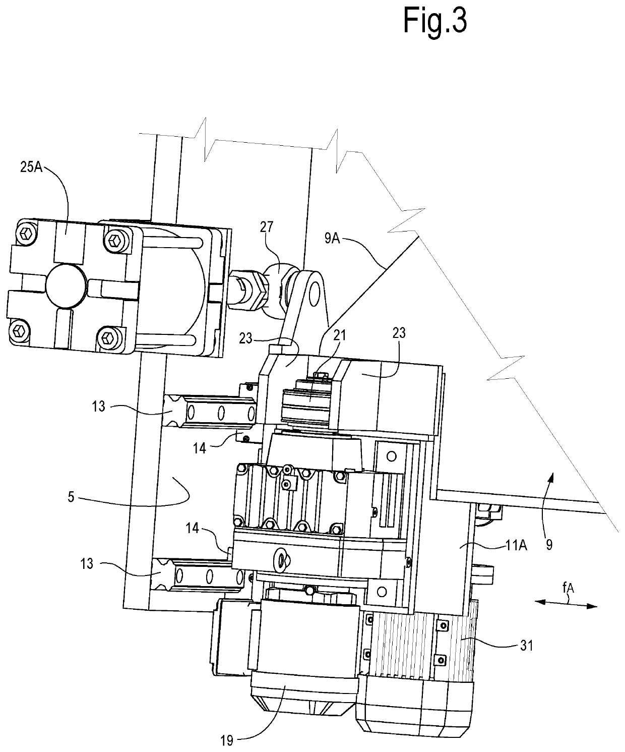
[0022]The greater rigidity offered by the linear guides reduces the flexural deformability of the beam and consequently the deflection that forms as a result of the stress applied by the cylindrical surface of the roller against the doctor blade mounted on the beam.

Problems solved by technology

However, they have some limits.
In particular, they are prone to breakages and can be difficult to maintain and use.
These systems are of much simpler construction than flexible systems, but also have some drawbacks, in particular due to the difficulty of adapting the shape of the doctor blade to the cylindrical surface of the cylinder.
This makes it necessary for the doctor blade to be thrust against the cylindrical surface with very high pressures, resulting in increased frictions and torques, as well as wear.
The beam thus mounted is prone to deformations and vibrations in a non-negligible manner under the thrust generated by the contact pressure between the doctor blade and the cylinder.
This deformation can cause difficulties in the operation of the cylinder and of the doctor blade co-acting therewith.

Method used


Image

  • Rigid and flexible doctor blade holder and system comprising a cylinder and a doctor blade holder
  • Rigid and flexible doctor blade holder and system comprising a cylinder and a doctor blade holder
  • Rigid and flexible doctor blade holder and system comprising a cylinder and a doctor blade holder

Examples


Embodiment Construction

[0052]The following detailed description of embodiments given by way of example refers to the accompanying drawings. The same reference numbers in different drawings identify identical or similar elements. Moreover, the drawings are not necessarily to scale. The following detailed description does not limit the invention. Rather, the scope of the invention is defined by the accompanying claims.

[0053]Reference in the description to “an embodiment” or “the embodiment” or “some embodiments” means that a particular characteristic, structure or element described in relation to an embodiment is included in at least one embodiment of the object described. Therefore, the phrase “in an embodiment” or “in the embodiment” or “in some embodiments” used in the description does not necessarily refer to the same embodiment or embodiments. Furthermore, the particular characteristics, structures or elements may be combined in any appropriate manner in one or more embodiments.

[0054]Hereunder, there w...


PUM


Abstract

A doctor blade holder (7) for a doctor blade (43) adapted to coact with a cylindrical surface (1S) of a rotating cylinder (1). A plurality of fingers (35) are mounted on a beam (9), hinged around a rotation axis (37A) and configured to cumulatively form a housing seat (41) for the doctor blade (43). The fingers (35) are pivotable independently from one another around the rotation axis (37A). At least one elastic thrust member (51) is configured and arranged to generate a thrust on the fingers (35) to make them pivot around the rotation axis (37A). Each finger (35) has a locking element (67), to rigidly lock the finger to the beam (9).

Description

TECHNICAL FIELD[0001]The present invention relates to a doctor blade holder, for example for a creping doctor blade co-acting with a Yankee cylinder or for any doctor blade co-acting with the cylindrical surface of a cylinder or roller rotating around its axis.BACKGROUND ART[0002]In paper making machines, in particular tissue paper, a Yankee cylinder is normally used to dry the paper before winding it in a reel. One or more doctor blades co-act with the Yankee cylinder, with one of their edges pressed against the cylindrical surface of the Yankee cylinder. The purpose of these doctor blades is to detach the ply of cellulosic fibers from the Yankee cylinder and to carry out any other operations, for example cleaning. The Yankee cylinder can be provided with a single doctor blade or several doctor blades placed in sequence.[0003]Doctor blades are also used in combination with other types of cylinders or rollers, for example drying rollers.[0004]The doctor blade of a creping device is ...

Claims


Application Information

Patent Timeline
Patent Type & Authority Patents(United States)
IPC IPC(8): D21G3/04B31F1/14D21G3/00
CPCD21G3/005D21G3/04B31F1/14B31F1/145
Inventor GASPARI, ROBERTOORLANDINI, ANDREA
Owner ORADOC
Why Eureka
Try Eureka