
System and process for carbon dioxide removal of air of passenger cabins of vehicles

a technology for passenger cabins and carbon dioxide removal, which is applied in the direction of combustible gas purification/modification, other chemical processes, separation processes, etc., can solve the problems of recirculation of hvac systems, health risks of airborne nanoparticles from vehicle emissions, etc., to improve fuel economy, improve ventilation systems, and reduce energy load

Active Publication Date: 2020-05-12
JOHNSON MATTHEY PLC
View PDF20 Cites 2 Cited by
  • Summary
  • Abstract
  • Description
  • Claims
  • Application Information

AI Technical Summary

Benefits of technology

This patent involves improving ventilation systems for vehicles to reduce energy consumption and provide better air quality. One way to achieve this is by using a regenerable carbon dioxide adsorption assembly that can absorb and desorb carbon dioxide. This reduces the energy load associated with HVAC systems and improves the range and comfort of the vehicle. The system can also operate on full recirculation mode, which further enhances the purification of the air inside the cabin. This improves filter lifetimes and reduces the frequency of regeneration, ultimately reducing the energy load and improving the efficiency of the ventilation system.

Problems solved by technology

Reference 1 highlights that there are disadvantages associated with operating the HVAC system in recirculation mode, discussing in particular that a build-up of volatile organic compounds (VOCs) is observed when HVAC systems are operated in recirculation mode (especially in newer cars).
As Reference 2 explains, airborne nanoparticles from vehicle emissions pose health risks, particularly when driving in heavy traffic.
However, Reference 3 highlights a significant problem associated with the operation of HVAC systems in recirculation mode.

Method used


Image

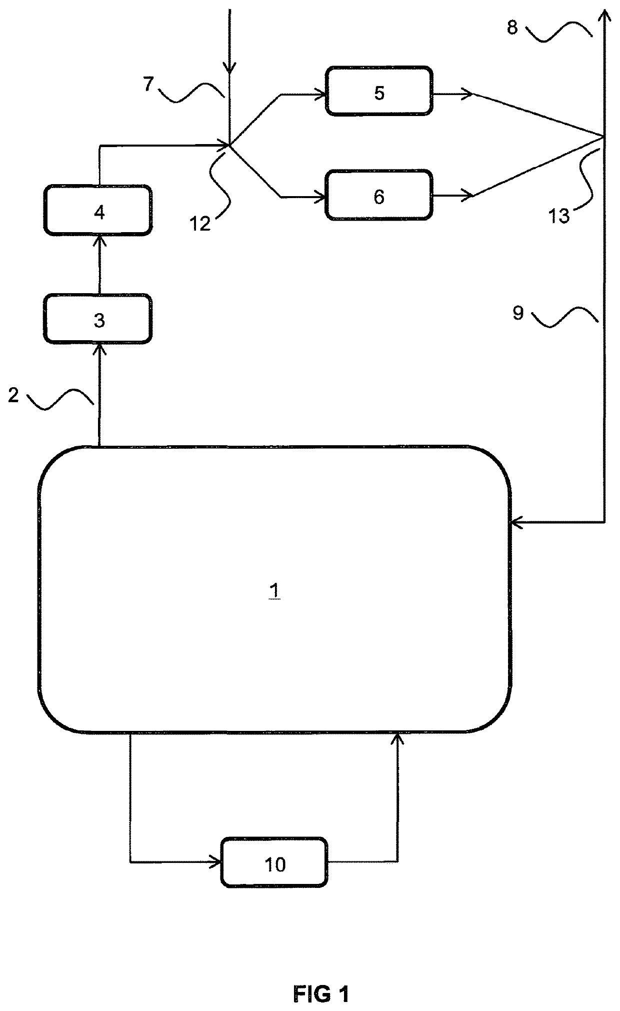
  • System and process for carbon dioxide removal of air of passenger cabins of vehicles
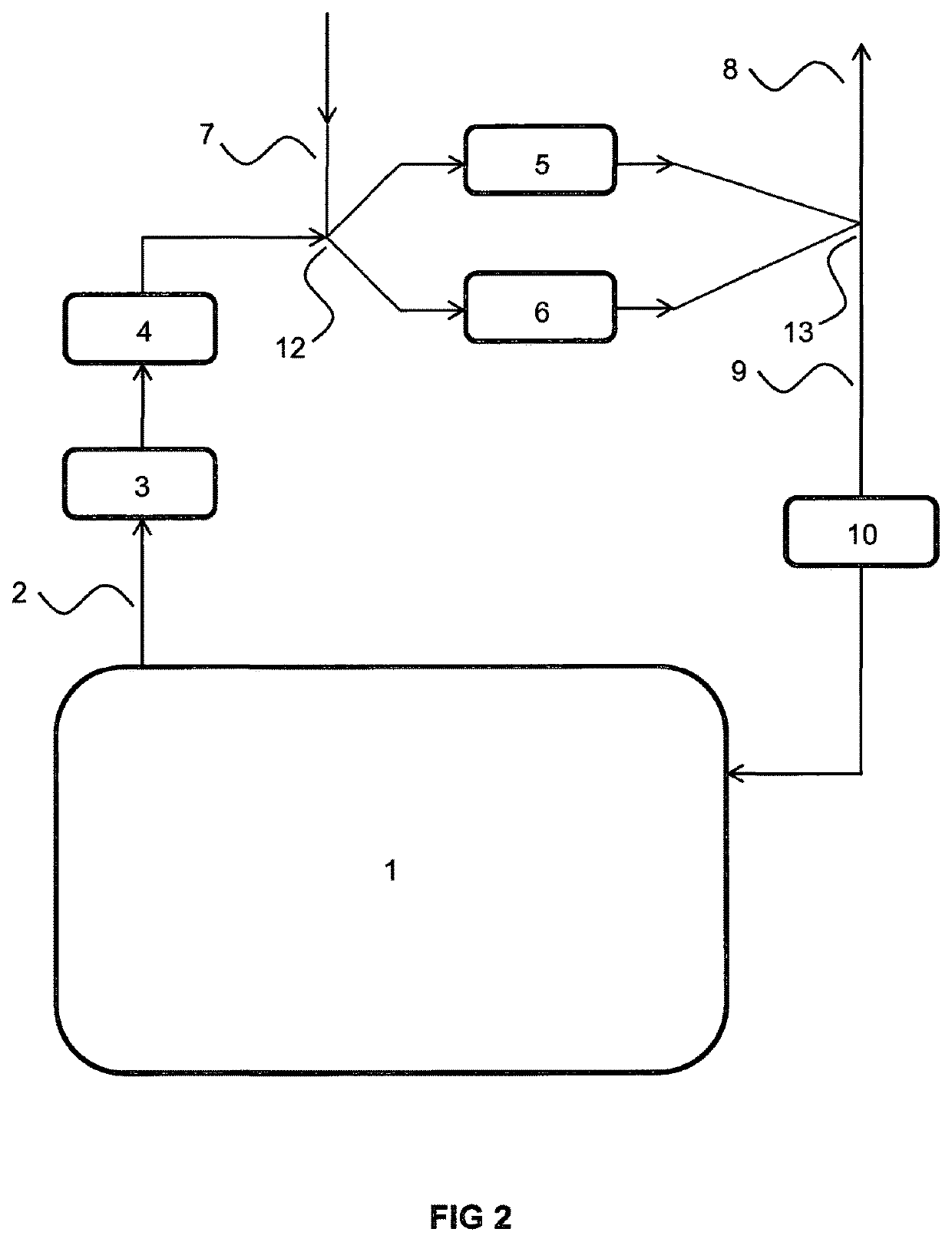
  • System and process for carbon dioxide removal of air of passenger cabins of vehicles
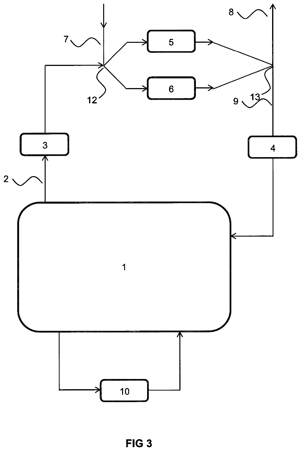
  • System and process for carbon dioxide removal of air of passenger cabins of vehicles

Examples


Embodiment Construction

[0036]Preferred and / or optional features of the invention will now be set out. Any aspect of the invention may be combined with any other aspect of the invention unless the context demands otherwise. Any of the preferred and / or optional features of any aspect may be combined, either singly or in combination, with any aspect of the invention unless the context demands otherwise.

Carbon Dioxide Removal Assembly

[0037]Regenerable carbon dioxide sorbent material is employed in the methods of the present invention. A range of regenerable carbon dioxide sorbent materials are known. Typically, regenerable carbon dioxide sorbent materials are regenerated by heating them to promote desorption of the sorbed carbon dioxide and flowing a desorption gas over the material to carry away the desorbed carbon dioxide. Additionally, the sorbent material may be exposed to a pressure below atmospheric pressure to encourage desorption. This can result in a lowering of the temperature required to effect des...


PUM

PropertyMeasurementUnit
temperatureaaaaaaaaaa

Abstract

The present invention relates to systems and methods for controlling the atmosphere in the cabin (1) of a vehicle. The system comprises a carbon dioxide removal conduit (2) comprising a regenerable carbon dioxide removal chamber (5,6) containing a carbon dioxide sorbent material and a regeneration circuit (7) arranged to expel the desorbed carbon dioxide at a location exterior (8) of the cabin (1) The system is operable to maintain a carbon dioxide level below 1000 ppm in the passenger cabin for a period of at least 5 minutes while restricting the flow of air from outside the vehicle into the passenger cabin to 10 L / s or less.

Description

FIELD OF THE INVENTION[0001]The present invention relates to systems and methods for controlling the atmosphere in the cabin of a vehicle.BACKGROUND OF THE INVENTION[0002]Heating, ventilation and air conditioning (HVAC) systems can be a significant contributor to the energy requirements of a vehicle. The high energy demand of the compressor in these systems can lead to a reduction of 8% to 12% in the mileage range of an internal combustion engine (ICE) vehicle, due to the impact on fuel economy. In an electric vehicle (EV), the HVAC system can lead to a reduction of 40% in the mileage range. Accordingly, reducing the energy load of HVAC systems is of considerable interest, as this has the potential to provide benefits associated with improved energy efficiency and fuel economy. Increasing the range of electric vehicles is also desirable.[0003]Reference 1 discusses the impact of vehicle air conditioning on fuel economy, tailpipe emissions and electric vehicle range. In order to reduc...

Claims


Application Information

Patent Timeline
Patent Type & Authority Patents(United States)
IPC IPC(8): B01D53/02B01J20/26B01J20/10B01J20/28B01J20/22B01J20/34B60H3/06B01D53/04B01J20/32
CPCB01J20/3425B60H3/06B01J20/3483B01J20/3244B01J20/22B01J20/265B01J20/103B60H3/0633B01J20/3242B01D53/04B01D53/0423B01J20/28042B01D2253/204B01D2258/06B01D2257/504B01D2253/25B01D2257/708B01D2259/401B01D2253/106B01D2253/202Y02C10/08B01D2253/108B60H2003/0691B01D2259/402B01D2259/4566B01D2259/414B01D2253/11B01D2259/40086B01D2259/4009Y02C20/40
Inventor LUISMAN, LUKE ALANAMIEIRO-FONSECA, ALVAROVAN LISHOUT, YOLANDAREED, GRAHAM
Owner JOHNSON MATTHEY PLC
Learn More