Fault current limiter

a current limiter and fault technology, applied in the field of fault current limiters, can solve the problems of adversely affecting the reliability of the device, increasing short-circuit current, and high power loss, and achieve the effects of compact structure, fast energy transfer, and easy engineering

Active Publication Date: 2020-05-12
HUAZHONG UNIV OF SCI & TECH
View PDF5 Cites 1 Cited by
  • Summary
  • Abstract
  • Description
  • Claims
  • Application Information

AI Technical Summary

Benefits of technology

[0009]Based on the characteristics of the resistive and the inductive superconducting fault current limiters, a topological structure of the hybrid superconducting fault current limiter including resistive components and inductive components is put forward to protect the DC system when the short-circuit fault occurs. The hybrid superconducting fault current limiter is capable of fast energy transfer, is easy to engineer, has a compact structure, and exhibits outstanding performance index in cost, size, complexity, and response speed.
[0015]The inventive concept of the present disclosure of the invention comprises the topological structure of the hybrid superconducting fault current limiter. The superconducting inductor structure of the hybrid superconducting fault current limiter is connected in parallel to a shunt resistor, forming a main structure. When a fault develops, the inductors prevent the current from increasing, and the fault current is diverted to a resistor branch where the current-limiting resistor quickly takes effect, thus the peak current is quickly limited. In the main structure, the inductors have identical number of windings and identical structure. Magnetic fluxes of the inductors are forward coupled, and the inductors are connected in parallel to form a superconducting inductor structure. Magnetic fluxes are forward coupled so as to improve the overall superconducting inductor gain and reduce the adverse effect of inductance drop caused by parallel connection of the superconducting wires. Meanwhile, the two identical superconducting inductors are connected in parallel, when a fault develops, the two inductors can jointly bear the current shock, and each inductor bears only a half of the current shock of the superconducting inductor structure, thus reducing the influence of fault current on the superconducting inductors. In the main structure, the superconducting inductor structure is connected to the direct current circuit breaker in series, and the direct current circuit breaker is connected to the first fixed resistor in parallel. In normal operation of the DC system, the direct current circuit breaker is switched on, and the current flows through the series branch of the superconducting inductor structure. The fault current limiter works as a smoothing reactor. When a fault develops, the direct current circuit breaker is switched off, and the superconducting inductor structure works to divert the fault current to the shunt resistor so that the peak current is limited and the superconducting inductor structure is protected from damage caused by the fault current, meanwhile, the resistive component in the series branch ensures that the steady short-circuit current is also limited. Because the direct current circuit breaker is connected to the fixed resistor in parallel, the break voltage is suppressed, facilitating the switching of the direct current circuit breaker, and improving the stability of the switching. The direct current circuit breaker is light-weight, and the production cost is reduced. The metal oxide arresters are configured to prevent overvoltage of the inductor.
[0022]1. Compared with the fault current limiter in the prior art, the hybrid superconducting fault current limiter of the invention is capable of fast energy transfer, easy to engineer, has a compact structure, and exhibits outstanding performance index in cost, size, complexity, and response speed. Based on the characteristics of the resistive and the inductive superconducting fault current limiters, a topological structure of the hybrid superconducting fault current limiter including resistive components and inductive components is put forward to protect the DC system when the short-circuit fault occurs. In normal operation of the DC system, the fault current limiter works as a smoothing reactor, and has no energy consumption. When a fault develops, the fault current limiter can obviously limit the current and works to compensate the voltage drop of the DC system. Because the superconducting inductor structure of the current limiter is connected to a shunt resistor in parallel, when a fault occurs, the fault current is quickly diverted to the resistor branch, and the peak current is limited. When the direct current circuit breaker is switched off, the current limiting function of the current limiter can be further improved, and the steady short-circuit current is limited. The superconducting inductors are unlikely to quench during the current limiting process, thus ensuring the security and stability of the superconducting structure.
[0023]2. The hybrid superconducting fault current limiter based on fast energy transfer can be applied to DC low-voltage lines and DC high-voltage transmission lines, and can respond to monopolar grounding fault and bipolar short-circuit fault, thus the requirements for fault current limiter as an important device for power grid construction under the condition that the short-circuit capacity of the power grid are increasing are satisfied, and relay protection configuration and stability of the DC system are maintained, meanwhile, the transient stability and the security in the steady state of the power grid are ensured.
[0024]3. The hybrid superconducting fault current limiter of the invention is capable of fast energy transfer, easy to engineer, has a compact structure, and exhibits outstanding performance index in cost, size, complexity, and response speed.

Problems solved by technology

However, with the rapid development of the power transmission network, the short-circuit current is increasingly large, and conventional high voltage DC circuit breakers are unable to interrupt the fault current.
In addition, conventional high voltage DC circuit breakers are structurally complex and bulky, and lead to high power losses.
Resistive fault current limiters are not efficient in limiting the short-circuit current peak and controlling the quenching process, thus adversely affecting the reliability of the devices.
Inductive fault current limiters are not efficient in suppressing steady-state short-circuit current, and require a large amount of iron metal to carry out their function, meaning that inductive FCLs are much bigger and heavier than resistive FCLs.

Method used


Image

  • Fault current limiter
  • Fault current limiter
  • Fault current limiter

Examples


Embodiment Construction

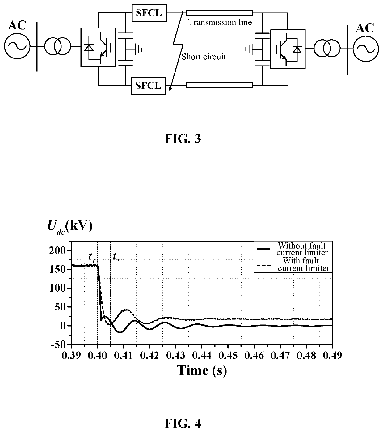
[0035]For further illustrating the invention, experiments detailing a hybrid superconducting fault current limiter are described below. It should be noted that the following examples are intended to describe and not to limit the invention.

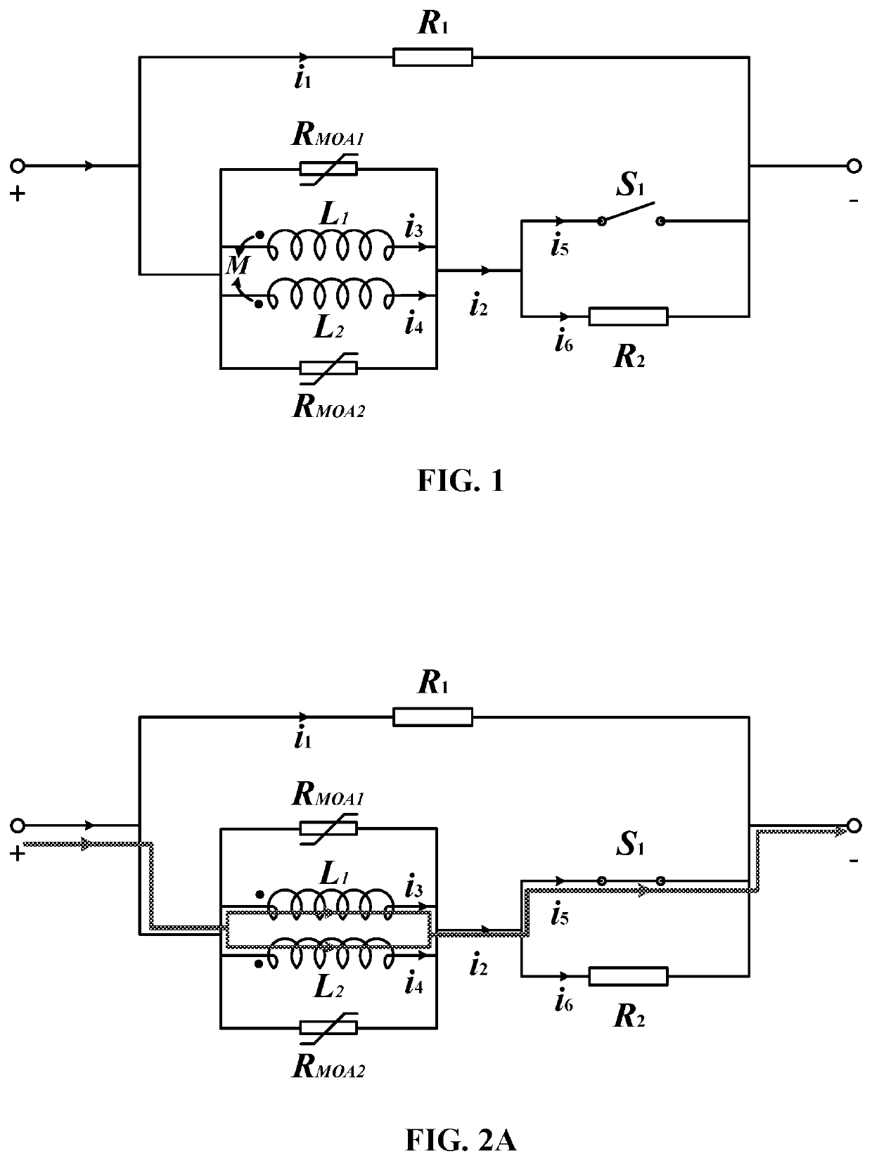
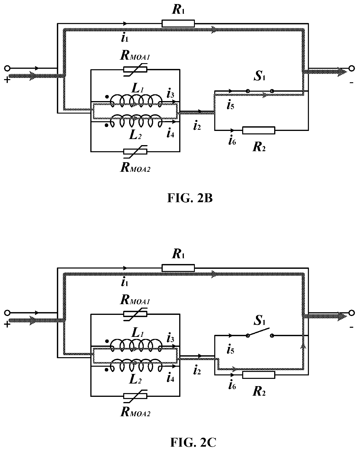
[0036]A hybrid superconducting fault current limiter comprises two inductors, a direct current circuit breaker, a shunt resistor, a first fixed resistor, and metal oxide arresters. The inductors comprise wound superconducting wires. The inductors have identical number of windings and identical structure. Magnetic fluxes of the inductors are forward coupled, and the inductors are connected in parallel to form a superconducting inductor structure. The direct current circuit breaker and the superconducting inductor structure are connected in series to form a series branch. The shunt resistor is connected in parallel to the series branch. The first fixed resistor is connected in parallel to the direct current circuit breaker. The metal oxide arresters ...


PUM

PropertyMeasurementUnit
peak currentaaaaaaaaaa
equivalent resistanceaaaaaaaaaa

Abstract

A fault current limiter, including: two inductors, a direct current circuit breaker, a shunt resistor, a first fixed resistor, and metal oxide arresters. The two inductors include wound superconducting wires. The inductors have identical number of windings and identical structure. Magnetic fluxes of the inductors are forward coupled, and the inductors are connected in parallel to form a superconducting inductor structure. The direct current circuit breaker and the superconducting inductor structure are connected in series to form a series branch. The shunt resistor is connected in parallel to the series branch. The first fixed resistor is connected in parallel to the direct current circuit breaker. The metal oxide arresters are two in number, and are connected to two ends of the inductors in parallel.

Description

CROSS-REFERENCE TO RELATED APPLICATIONS[0001]This application is a continuation in part of U.S. Ser. No. 15 / 491,954 filed on Apr. 19, 2017, now pending, which claims the benefit of Chinese Patent Application No. 201720175479.1 filed Feb. 27, 2017. The contents of all of the aforementioned applications, including any intervening amendments thereto, are incorporated herein by reference. Inquiries from the public to applicants or assignees concerning this document or the related applications should be directed to: Matthias Scholl P. C., Attn.: Dr. Matthias Scholl Esq., 245 First Street, 18th Floor, and Cambridge, Mass. 02142.BACKGROUND OF THE INVENTIONField of the Invention[0002]The invention relates to a fault current limiter.Description of the Related Art[0003]High voltage direct current (DC) circuit breakers are considered to be one of the effective ways to solve the problem of short-circuit fault in DC power systems. However, with the rapid development of the power transmission net...

Claims


Application Information

Patent Timeline
Patent Type & Authority Patents(United States)
IPC IPC(8): H02H7/00H01H33/59H02H9/00H01F38/02H02H9/02H01H9/54H01F6/00H01F1/00
CPCH01H33/596H02H9/023H01F38/023H02H7/001H01H9/548H01H9/547H01F2006/001Y02E40/68H01F1/00Y02E40/60
Inventor REN, LILIANG, SIYUANTANG, YUEJINXU, YINGXIA, ZHONGWANG, ZUOSHUAISHI, JINGLI, JINGDONGZHANG, LIHUIYAN, SINIANYANG, ZHANGWEIZHANG, YI
Owner HUAZHONG UNIV OF SCI & TECH
Why Eureka
Try Eureka