Winding device

a technology of winding device and winding shaft, which is applied in the direction of fastenings, footwear, buckles, etc., can solve the problems of high manufacturing cost, increased handling size, and difficulty in reducing the size of the device, so as to reduce the number of components, simplify the structure, and reduce the effect of weigh

Active Publication Date: 2020-05-26
ALPEN CO LTD
View PDF29 Cites 5 Cited by
  • Summary
  • Abstract
  • Description
  • Claims
  • Application Information

AI Technical Summary

Benefits of technology

[0027](1) In the above-described winding device of the present invention, rotation of the dial can be controlled by the dial including the annular gear with a simple structure and by the drum accommodation portion including the pawl.
[0028]This reduces the number of components of the winding device, simplifies the structure, reduces the size and weight of the winding device, increases the strength, durability, and reliability, and decreases the amount of time and effort needed for assembly and maintenance.
[0029](2) In the winding device of the present invention, the pawl protrudes outward or inward from a spring portion arranged concyclically with a cylindrical annular wall that configures the drum accommodation portion. This simplifies the structure and reduces the device in size.
[0030](3) In the winding device of the present invention, the pawl protrudes outward from a spring portion located in a lower part of a cylindrical annular wall that configures the drum accommodation portion. This reduces the thickness of the winding device to reduce the size of the winding device and protects the spring portion.
[0031](4) In the winding device of the present invention, the pawl is integrated with a cylindrical annular wall that configures the accommodation portion. This increases the strength of the device and simplifies the structure of the device, thereby significantly reducing the amount of time and effort needed for assembly and maintenance.
[0032](5) In the winding device of the present invention, the pawl protrudes outward from a spring portion formed by cutting out a cylindrical annular wall that configures the drum accommodation portion, and elastic deformation of the spring portion toward an inside of the drum accommodation portion causes the pawl to slide up and over the projection of the annular gear, which is formed to be cylindrical on the circumferential portion of the dial, allowing the dial to rotate. This simplifies the structures of the pawl that controls rotation of the dial and the spring that moves the position of the pawl. This also increases the strength of the pawl and the spring.

Problems solved by technology

These conventional winding devices have problems such as (1) the structure of the dial that rotates the drum and changes the engaged state of the dial and the drum is complicated, (2) multiple components need to be assembled in order to configure the structure of the dial that rotates the drum and changes the engaged state of the dial and the drum, (3) the structure of a pawl configuring a ratchet mechanism that controls rotation of the dial and the structure of a spring that moves the position of the pawl are complicated, (4) multiple components need to be assembled in order to configure the structure of a pawl configuring a ratchet mechanism that controls rotation of the dial and the structure of a spring that moves the position of the pawl, and (5) a handle increases in size when forming a gear that includes projections and troughs extending radially on the inner surface of the dial.
The above-described winding devices have problems such as difficulty in reducing the size of the devices, high manufacturing costs, limits in the reliability and usage of the product if components have a decreased strength, and lengthy and intensive assembly and maintenance processes.

Method used


Image

  • Winding device
  • Winding device
  • Winding device

Examples


first embodiment

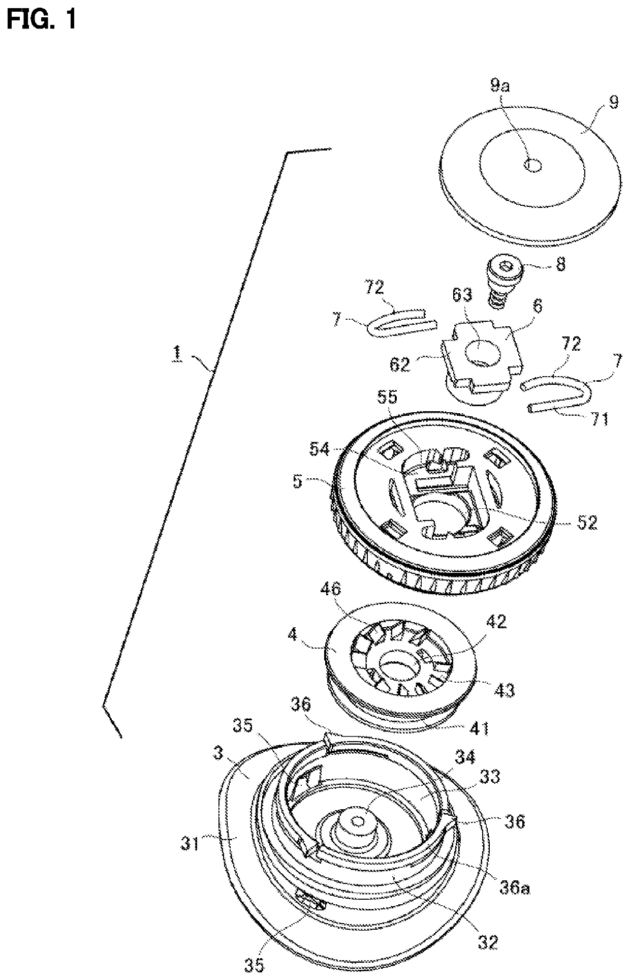
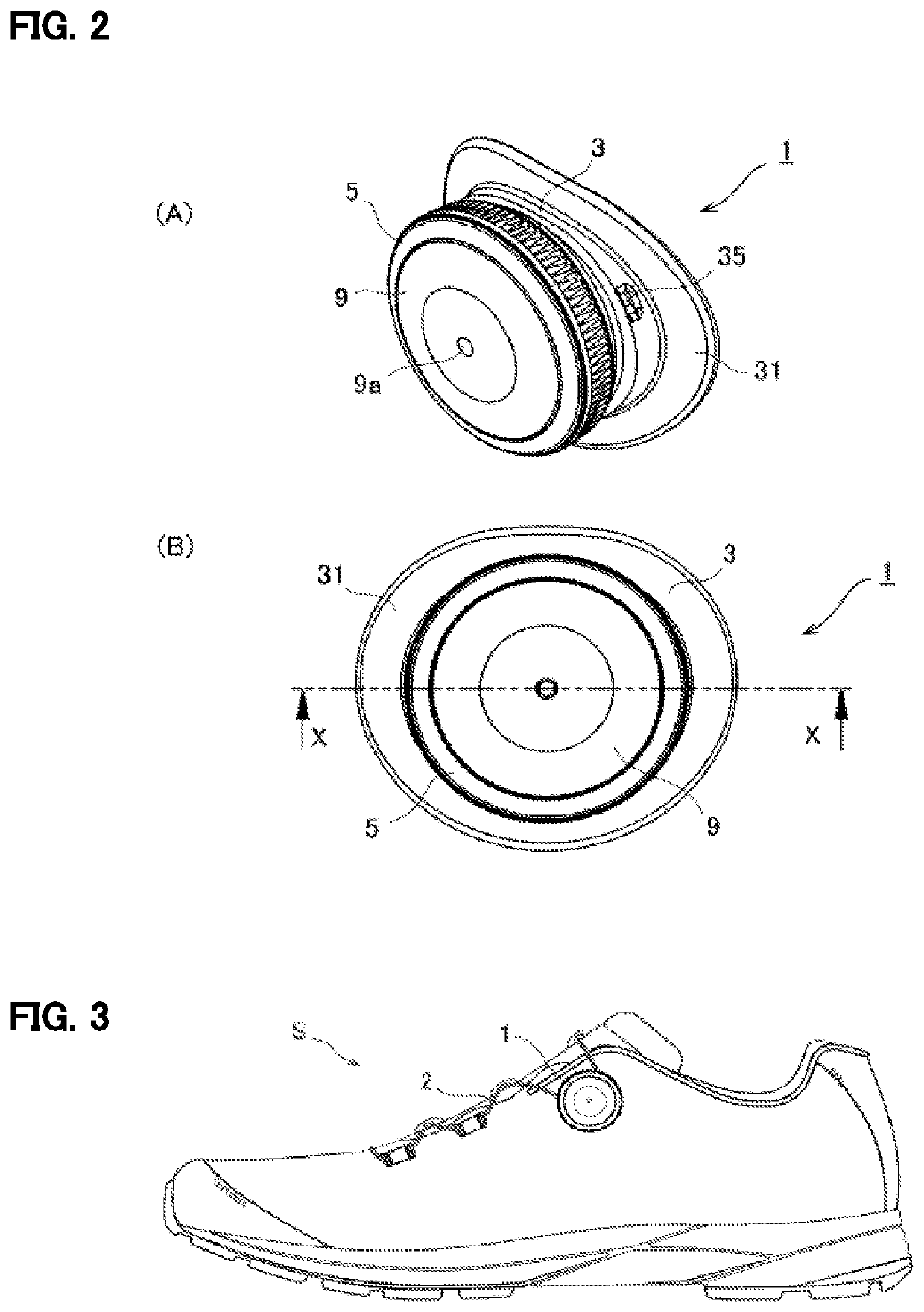
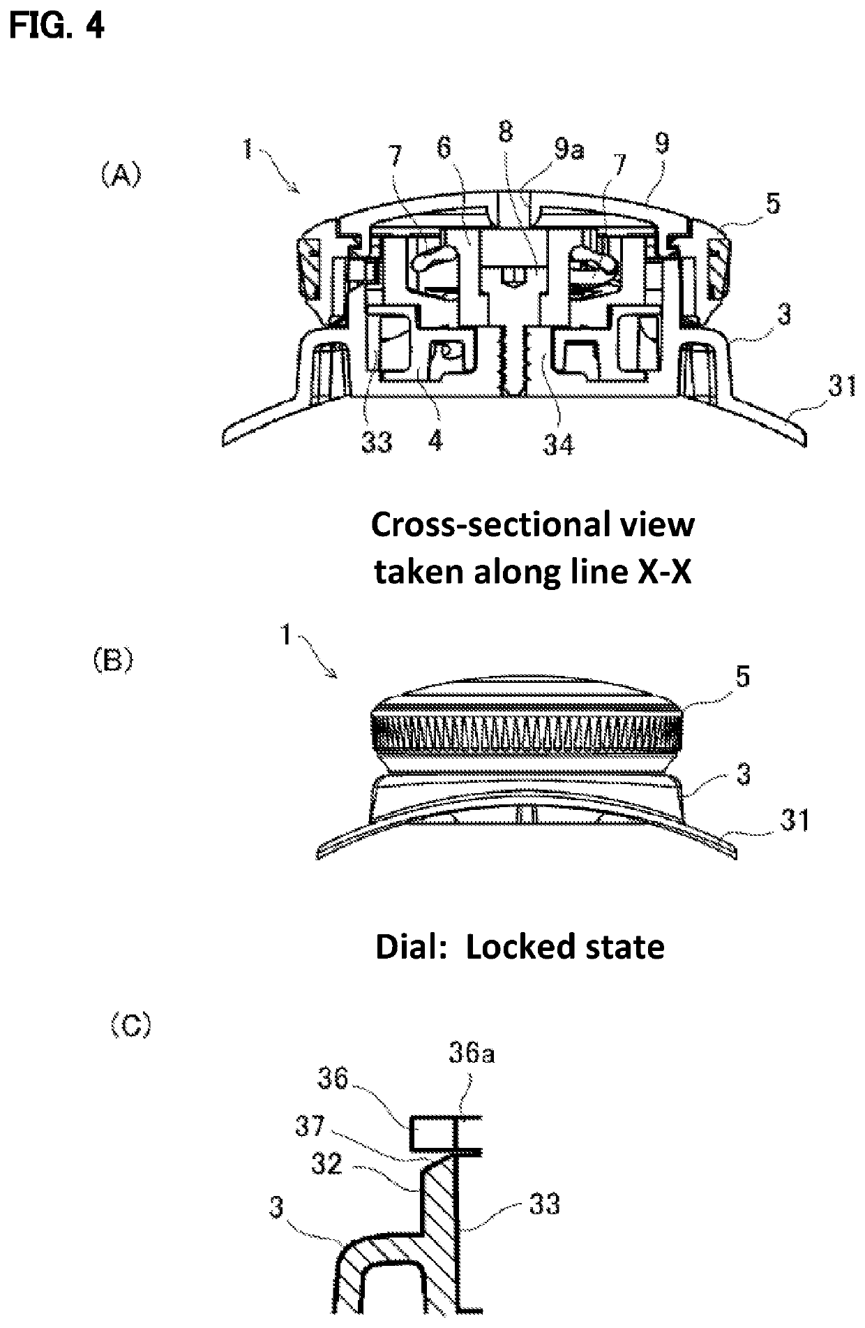
[0114]An embodiment ( FIGS. 1 to 10) in which the winding device of the present invention is applied to a winding device that winds the shoelaces of sport shoes will now be described.

[0115]The internal structure and the advantages of the embodiments of the winding device of the present invention have already been partially disclosed by the applicants of the present application in Japanese Patent Application No. 2013-127574 (Japanese Laid-Open Patent Publication No. 2015-293), Japanese Patent Application No. 2013-127612 (Japanese Laid-Open Patent Publication No. 2015-297), and Japanese Patent Application No. 2014-163867 (Japanese Laid-Open Patent Publication No. 2016-36679).

[0116]FIG. 3 shows a shoelace winding device 1 according to an embodiment of the present invention and a shoe S provided with the shoelace winding device 1 at a position corresponding to an ankle. In the shoe S, the instep part of the shoe S can be tightened with a shoelace 2 configured by, for example, a plastic-...

second embodiment

[0175]For example, as another embodiment ( FIGS. 11 to 17), a shoelace winding device 102 including a base 3a located at the heel part of the shoe S as shown in FIG. 13 may be embodied.

[0176]Each of the embodiments in this specification has the same structure as the first embodiment, which will not be described.

[0177]In the shoelace winding device 102 according to the second embodiment, the shape of the flange 31 of the base 3 of the shoelace winding device 1 according to the first embodiment is curved to conform to the shape of the heel part. Further, a flange 31a in which the shape of the flange 31 is entirely changed to be like a flower petal is employed.

[0178]Additionally, in the shoelace winding device 102, the annular wall 32, the rotation shaft 34, the pawls 36, and the spring portions 36a of the shoelace winding device 1 according to the first embodiment are configured as a drum accommodation portion 33a, which is separate from the base 3a.

[0179]The drum accommodation porti...

third embodiment

[0184]The winding device of the present invention may be, as a further embodiment ( FIG. 18), embodied as a shoelace winding device 103. The shoelace winding device 103 does not include cutouts in the proximity of the pawls 36 of the annular wall 32, which configures the drum accommodation portion 33.

[0185]The third embodiment differs from the first embodiment in that the spring portions 36a are not included. Thus, at least one of the following numbered changes in structure needs to be employed so that the pawls 36 slide up and over the projections of the annular gear 53 and the dial 5 rotates only in a single direction.

[0186]1. Change the thickness or material of the annular wall 32 to increase the elasticity of the surrounding parts of the pawls 36.

[0187]2. Change the thickness or material of the dial 5 to increase the elasticity of the annular gear 53.

[0188]3. Use the pawls 36 or the projections of the annular gear 53 that are elastically deformable.

[0189]4. Increase the number o...


PUM


Abstract

A winding device 1 including a base 3 including a drum accommodation portion 33 that accommodates a drum 4 including upward teeth 46, the accommodation portion 33 being cylindrical and having a closed end, and a dial 5 including downward teeth (53) to rotate the drum 4. The dial 5 is moved to a locked state in which the downward teeth are engaged with the upward teeth 46 to transmit rotation of the dial 5 to the drum 4 and an unlocked state in which the downward teeth are disengaged from the upward teeth 46. The winding device 1 includes an annular gear (51) including projections and roots extending in the rotation axis direction of the dial 5 and a pawl 36 protruding from the drum accommodation portion 33. The pawl 36 is designed to engage with the annular gear. The annular gear and the pawl 36 control rotation of the dial.

Description

TECHNICAL FIELD[0001]The present invention relates to a winding device; more specifically, to a winding device suitable for tightening the laces of various types of shoes. In addition to tightening laces of sport shoes used for jogging, golf, and the like, the winding device can be used to tighten laces used to fasten other types of shoes, or other products such as hat laces.BACKGROUND ART[0002]Conventionally, as shoelace winding devices suitable for tightening shoelaces, shoelace winding devices that wind shoelaces around a drum by rotating a dial (disk-shaped knob) and cancel the engaged state of the dial and the drum to cancel tightening of shoelaces with a single touch of a button by pulling the dial have been proposed (refer to Patent Documents 1 to 8 described below).[0003]These conventional winding devices have problems such as (1) the structure of the dial that rotates the drum and changes the engaged state of the dial and the drum is complicated, (2) multiple components nee...

Claims


Application Information

Patent Timeline
Patent Type & Authority Patents(United States)
IPC IPC(8): A43C11/16A43C11/00A43B5/04A43C11/20A44B11/12B65H75/38
CPCA44B11/12A43C11/165A43C11/00B65H75/38A43B5/04A43C11/20
Inventor KAWANO, FUMIYOSHI
Owner ALPEN CO LTD
Why Eureka
Try Eureka