Method for producing a rotor blade

a rotor blade and rotor blade technology, which is applied in the direction of turbines, efficient propulsion technologies, machines/engines, etc., can solve the problems of difficult to achieve a wall thickness of 1 mm, complex geometries can be produced in the interior of the blade, and the known 3-d printing method can achieve the reduction of component strength, improve the efficiency and power of gas turbines, and reduce the thickness of the blade airfoil

Active Publication Date: 2020-06-02
SIEMENS ENERGY GLOBAL GMBH & CO KG
View PDF20 Cites 0 Cited by
  • Summary
  • Abstract
  • Description
  • Claims
  • Application Information

AI Technical Summary

Benefits of technology

[0009]Just as with steel reinforced concrete, the stays are intended to be aligned in the direction of the principal load. This applies especially to the load imposed by the centrifugal force during the operation of the gas turbine, which acts radially outward, i.e. in the direction of the blade tip, and increases continuously toward the blade tip. The reinforcement should therefore advantageously comprise at least one stay, which extends from a region of the rotor blade tip to the platform, and therefore through the entire blade airfoil in the direction of the load. Stabilization of the blade airfoil with respect to the occurring centrifugal force is thereby achieved.
[0010]Stability is improved even further if the reinforcement advantageously comprises a stay which extends from the region of the rotor blade tip to the fastening region. The entire rotor blade structure, from the fastening region at the rotor blade root to the tip of the blade airfoil, is thereby stabilized by a continuous stay.
[0011]As a further advantageous embodiment of the method, the above-described first part, which is cast around the reinforcement, comprises the fastening region. The fastening region, which generally has a tongue and groove structure resembling a firtree, generally comprises only a few cooling ducts, if any, and therefore has a less complex geometry. It is therefore also possible, in particular, to produce it using a reusable mold. Casting the fastening region furthermore ensures that said region has the required strength, and good cohesion with the reinforcement is produced.
[0016]It is advantageous if these cooling ducts are arranged in the region of the blade airfoil during the buildup of the second part.
[0018]It is advantageous if a rotor blade for a gas turbine is produced by one of the methods described up to this point.
[0020]The advantages achieved by means of the invention consist especially in that the weakness of 3-D printing materials is compensated by the use of a composite material and that such a method can be used for producing turbine blades. With the method, the wall thickness of the blade airfoil can be less, and it is also possible to produce longer rotor blades, thus improving the efficiency and power of the gas turbine.

Problems solved by technology

In the case of such a large component, it is generally difficult to implement a wall thickness of 1 mm.
In this process, very complex geometries can be produced in the interior of the blades.
The problem is that lower component strength is achieved with the known 3-D printing methods.

Method used


Image

  • Method for producing a rotor blade
  • Method for producing a rotor blade
  • Method for producing a rotor blade

Examples


Embodiment Construction

[0027]In all the figures, identical parts are provided with the same reference signs.

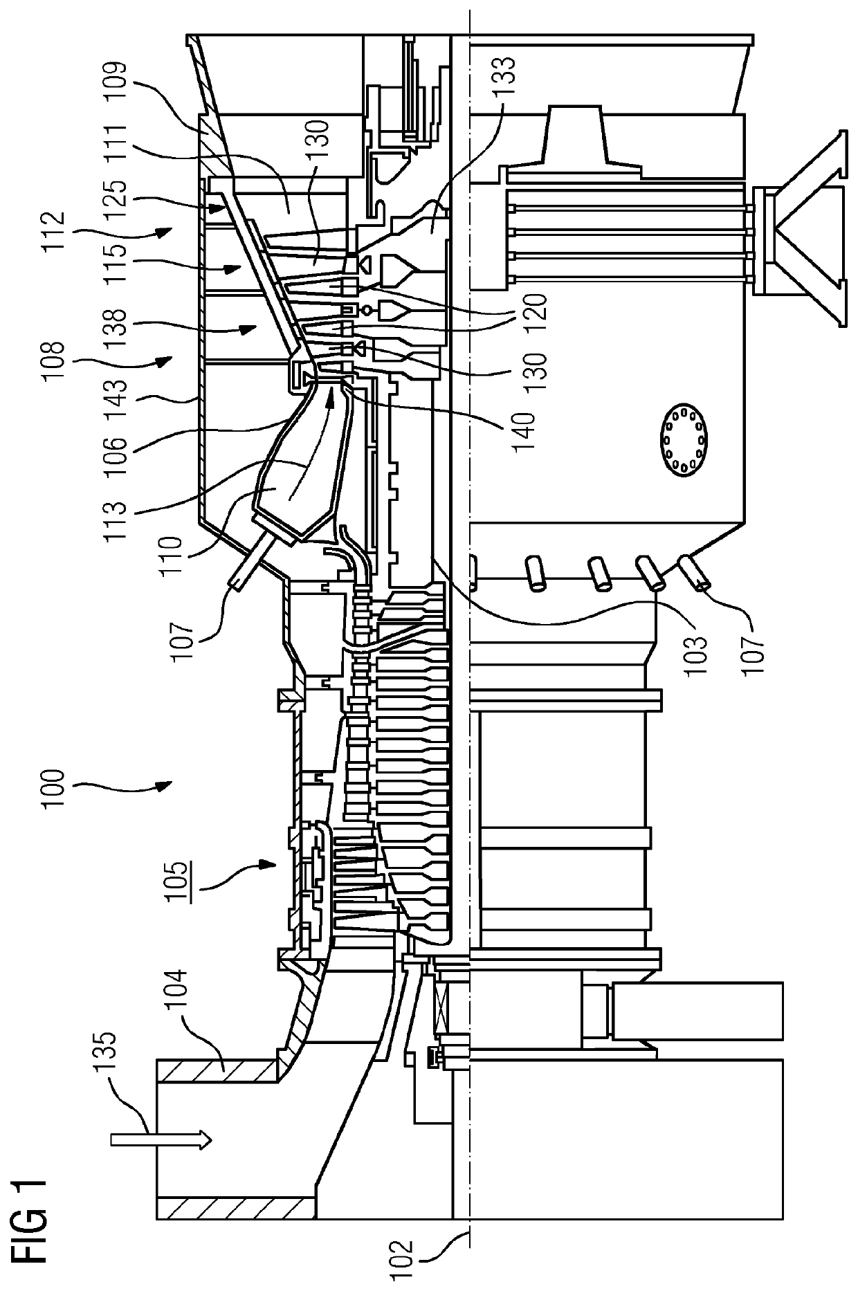
[0028]FIG. 1 shows a gas turbine 100 in a partial longitudinal section. A turbine is a continuous flow machine which converts the internal energy (enthalpy) of a flowing fluid (liquid or gas) into rotational energy and ultimately into mechanical driving energy.

[0029]In the interior, the gas turbine 100 has a rotor 103, which is mounted so as to rotate about an axis of rotation 102 (axial direction) and which is also referred to as a turbine rotor. Situated one after the other along the rotor 103 are an intake casing 104, a compressor 105, a toroidal combustion chamber 110, in particular an annular combustion chamber 106, having a plurality of coaxially arranged burners 107, a turbine 108 and the exhaust casing 109.

[0030]The annular combustion chamber 106 communicates with an annular hot gas duct 111. There, four turbine stages 112 arranged in series, for example, form the turbine 108. Each turbine s...


PUM

PropertyMeasurementUnit
thicknessaaaaaaaaaa
energyaaaaaaaaaa
rotational energyaaaaaaaaaa

Abstract

A method for producing a rotor blade for a gas turbine, the blade having a fastening region and a platform, on which a blade ending in a blade tip is arranged. The method is designed to facilitate a particular high efficiency of the gas turbine with a particularly resource-saving manner of production. The method includes: production of a reinforcement; casting of a first part of the rotor blade about at least one portion of the reinforcement; and construction of a second part of the rotor blade by a 3D-printing method.

Description

CROSS REFERENCE TO RELATED APPLICATIONS[0001]This application is the US National Stage of International Application No. PCT / EP2015 / 075384 filed Nov. 2, 2015, and claims the benefit thereof. The International Application claims the benefit of European Application No. EP14196293 filed Dec. 4, 2014. All of the applications are incorporated by reference herein in their entirety.FIELD OF INVENTION[0002]The invention relates to a method for producing a rotor blade for a gas turbine, the blade having a fastening region and a platform, on which a blade airfoil ending in a blade tip is arranged. It furthermore relates to a rotor blade of this kind.BACKGROUND OF INVENTION[0003]Rotor blades of the abovementioned type are used in gas turbines to convert the energy of a hot gas flow into rotational energy. They typically have a blade airfoil, which is penetrated by cavities for carrying cooling air and which is fastened on a “platform”. Adjoining the platform there is a fastening region for fast...

Claims


Application Information

Patent Timeline
Patent Type & Authority Patents(United States)
IPC IPC(8): F01D5/28B22D19/02B22F3/105B22F5/04B22F7/08F01D5/14B29L31/08
CPCB22F3/1055B22F5/04B22F7/08B22D19/02F01D5/147F01D5/282F05D2230/22F05D2220/32Y02P10/295Y02T50/672F05D2230/31F05D2230/21B29L2031/08B22F10/00B22F10/28Y02P10/25Y02T50/60
Inventor FELWOR, DAVID
Owner SIEMENS ENERGY GLOBAL GMBH & CO KG
Why Eureka
Try Eureka