Speed reducing device having power source

a technology of speed reducing device and power source, which is applied in the direction of gearing details, mechanical equipment, gearing, etc., can solve the problems of inconvenient application of connection structure to reducer and motor, inability to drive a large-sized load, and inability to meet the needs of industrial robotic arm or power assisting device, etc., to achieve the effect of reducing the weight and volume of the speed reducing devi

Active Publication Date: 2020-06-09
DELTA ELECTRONICS INC
View PDF16 Cites 0 Cited by
  • Summary
  • Abstract
  • Description
  • Claims
  • Application Information

AI Technical Summary

Benefits of technology

[0007]An object of the present invention provides a speed reducing device comprising a motor and a speed reducing mechanism. The motor and the speed reducing mechanism are combined together without the use of a connection structure (e.g., a shaft coupling or a gear box). Since the motor and the speed reducing mechanism are combined as an integral structure, the weight and volume of the speed reducing device are reduced.
[0008]Another object of the present invention provides a speed reducing device having a power source. The speed reducing device is capable of achieving dynamic balance, high rigidness, and high reduction ratio and driving a high load.

Problems solved by technology

In other words, it is difficult to drive a large-sized load.
In other words, the connection structure for connecting the reducer and the motor cannot be applied to the device that requires light weight and compact space.
For example, the connection structure is not suitably applied to an industrial robotic arm or a power assisting device.
However, since this reducer uses a mono-cycloidal set (i.e., a single cycloid), some drawbacks occur.
For example, when the reducer is operated at a high speed, it is difficult to maintain the dynamic balance state.
Consequently, the operation of the reducer results in high vibration.

Method used


Image

  • Speed reducing device having power source
  • Speed reducing device having power source
  • Speed reducing device having power source

Examples


first embodiment

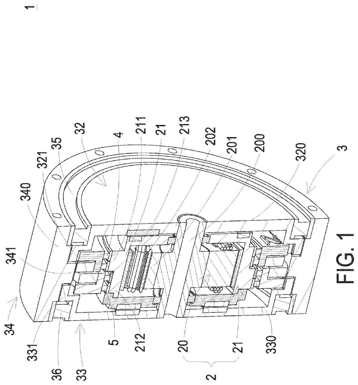
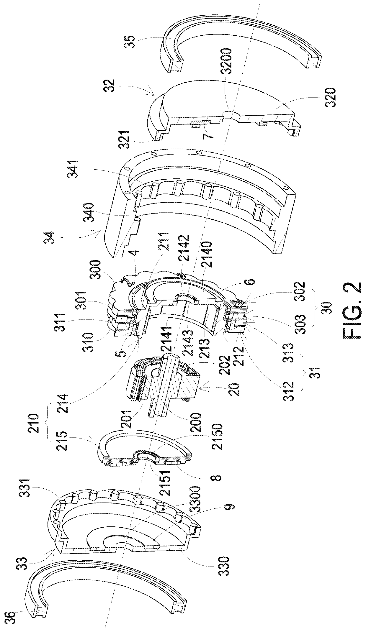
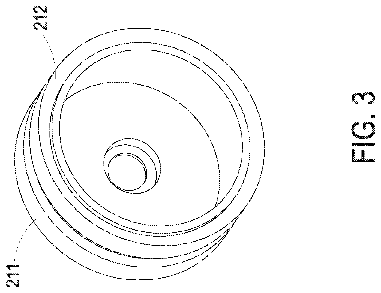
[0021]Please refer to FIGS. 1, 2 and 3. FIG. 1 is a schematic cutaway view illustrating a speed reducing device having a power source according to the present invention. FIG. 2 is a schematic exploded view illustrating the speed reducing device of FIG. 1. FIG. 3 is a schematic perspective view illustrating a rotator portion of a motor of the speed reducing device of FIG. 1. The speed reducing device having a power source 1 (hereinafter referred to as the speed reducing device 1) can be applied to various power mechanical devices such as industrial robotic arms or power assisting devices in order to provide a speed reducing function.

[0022]In this embodiment, the speed reducing device 1 is a two-stage cycloid reducer. The speed reducing device 1 comprises a motor 2 and a speed reducing mechanism 3. The motor 2 is served as a power source.

[0023]In an embodiment, the motor 2 is disposed within the speed reducing mechanism 3. For example, the motor 2 is a radial-flux motor. The motor 2 c...

second embodiment

[0043]FIG. 5 is a schematic cutaway view illustrating a speed reducing device having a power source according to the present invention. In this embodiment, the rotator portion 21 comprises the first rotator casing214 as shown in FIG. 4. As shown in FIG. 5, the first rotator casing bearing 2143 of the rotator casing bearing set is arranged between an inner periphery of the first reducer casing 320 and an outer periphery of the rotator casing assembly 210, and the second rotator casing bearing 2151 of the rotator casing bearing set is arranged between an inner periphery of the second reducer casing 330 and the outer periphery of the rotator casing assembly 210. In response to the magnetic interaction between the rotator portion 21 and the stator portion 20, the rotator portion 21 is rotated relative to the stator portion 20 through the rotator casing bearing set.

third embodiment

[0044]FIG. 6 is a schematic exploded view illustrating a speed reducing device having a power source according to the present invention. In this embodiment, the motor 2 is an axial-flux motor. Consequently, the overall thickness of the speed reducing device is reduced. As shown in FIG. 6, the motor 2 comprises a stator portion 60, a rotator portion 61 and a shaft portion 62. The stator portion 60 and the rotator portion 61 are installed on the shaft portion 62. That is, the shaft portion 62 is located at the central parts of the stator portion 60 and the rotator portion 61. In this embodiment, the rotator portion 61 comprises a rotator casing assembly 610, a first eccentric ring 611 and a second eccentric ring 612. The rotator casing assembly 610 has a hollow structure for accommodating the stator portion 60 and a part of the shaft portion 62. When the shaft portion 62 is accommodated within the hollow structure of the rotator casing assembly 610, a first end and a second end of the...


PUM


Abstract

A speed reducing device includes a motor and a speed reducing mechanism. The motor includes a stator portion, a shaft portion and rotator portion. The rotator portion includes first and second eccentric rings. The speed reducing mechanism includes first, second and third roller assemblies and first and second cycloid disc sets. These roller assemblies include first rollers, second rollers and third rollers. The first cycloid disc set is mounted around the first eccentric ring, and includes first teeth and second teeth. The second cycloid disc set is mounted around the second eccentric ring, and includes third teeth and fourth teeth. The first teeth are contacted with the first rollers. The third teeth are contacted with the second rollers. The second teeth and the fourth teeth are contacted with the third rollers.

Description

CROSS-REFERENCE TO RELATED APPLICATION[0001]This application claims the benefit of U.S. Provisional Application No. 62 / 524,290 filed on Jun. 23, 2017, and entitled “POWER GEAR”, the entirety of which is hereby incorporated by reference.FIELD OF THE INVENTION[0002]The present invention relates to a speed reducing device, and more particularly to a speed reducing device having a power source.BACKGROUND OF THE INVENTION[0003]Generally, a motor is operated at a high speed and a low torsion force. In other words, it is difficult to drive a large-sized load. Consequently, for allowing the motor to drive a heavy object, a reducer is used for reducing the rotating speed of the motor and increasing the torsion force.[0004]Conventionally, the reducer and the motor are separate components. It is necessary to connect the reducer with the motor through an additional connection structure such as a shaft coupling or a gear box. In such way, the volume and weight of the overall structure of the red...

Claims


Application Information

Patent Timeline
Patent Type & Authority Patents(United States)
IPC IPC(8): F16H1/32H02K7/116F16H57/02H02K7/102
CPCF16H57/02F16H1/32H02K7/102H02K7/116F16H2001/327F16H2057/02034
Inventor TSAI, CHING-HSIUNGWU, JIA-MINGHUANG, YU-XIANHUNG, KUO-YUANHSU, YOU-CHIUAN
Owner DELTA ELECTRONICS INC
Why Eureka
Try Eureka