Internet-based remote control and monitoring system for commercial doors using mobile devices

a technology of remote control and monitoring system, which is applied in the field of remote control of large industrial/commercial doors, can solve the problems that the use of motion sensors or load sensors is typically not effective for such doors, and achieve the effect of convenient scalabl

Active Publication Date: 2020-06-23
WICHITA STATE UNIVERSITY
View PDF5 Cites 4 Cited by
  • Summary
  • Abstract
  • Description
  • Claims
  • Application Information

AI Technical Summary

Benefits of technology

[0006]It would thus be desirable to provide means for enabling the user to control the door unit without using a mounted door panel or dedicated remote control devices. Thus, the invention provides a mobile application that enables the user to control and monitor his or her door unit from any distance. The user can monitor the door status by looking at live streaming video of the door in the mobile application. This is particularly useful for giant commercial “lift” doors. Using motion sensors or load sensors is typically not effective for such doors because they do not reliably prevent the door from hitting and damaging objects in the door's path (e.g., cattle or expensive machinery). The live streaming video of the invention provides feedback such as indicating the position of the door prior to and / or after remotely commanding the door unit to open or close. Users are enabled to securely manage multiple doors from one user application (“app”) loaded on a mobile device, and can provide them with a log including the history of each door's status. In addition, the invention is easily scalable so that an unlimited number of users could control and monitor many doors on their mobile devices using the same app.

Problems solved by technology

Using motion sensors or load sensors is typically not effective for such doors because they do not reliably prevent the door from hitting and damaging objects in the door's path (e.g., cattle or expensive machinery).

Method used


Image

  • Internet-based remote control and monitoring system for commercial doors using mobile devices
  • Internet-based remote control and monitoring system for commercial doors using mobile devices
  • Internet-based remote control and monitoring system for commercial doors using mobile devices

Examples


Embodiment Construction

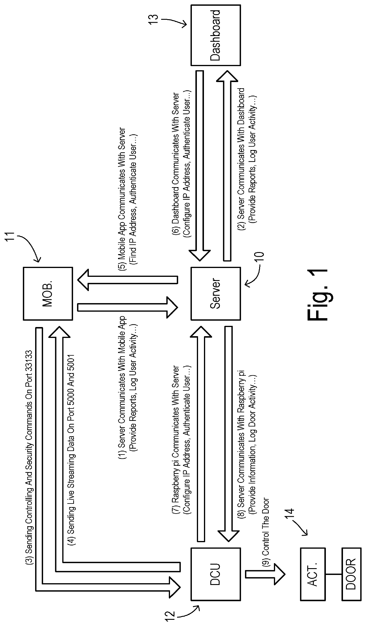
[0018]This invention may include a mobile application that enables remote control and real-time camera monitoring of commercial doors (e.g., big hydraulic doors, lift doors, warehouse doors) from a mobile device such as a cell phone or tablet over the Internet from anywhere which provides access to a central server (with an integrated or separate backend database) and a door controller unit at each controlled door closure. The mobile app is universal and could be seamlessly used on any Android, iPhone, or Windows mobile devices. The backend database may provide online management panel (i.e., dashboard) for clients wherein multiple doors are to be controlled and monitored, and provides report logs for managers in charge. The system can handle as many cameras per door as needed for monitoring. It also includes security features for the users and managers, and employs a secure communication protocol to carry out these operations.

[0019]As shown in FIG. 1, a main central server 10 commun...


PUM


Abstract

A remote control door closure operating system is based on a central server with a backend database identifying a collection of controllable doors and a plurality of authorized users and corresponding credentials. A door interface unit is adapted to communicate with an authorized user to supply a live video stream of a respective door and to execute door opening and closing commands from the authorized user. A mobile device has a user application program configured to interact with the central server and door interface unit in order to 1) obtain configuration data, 2) authenticate the authorized user, 3) receive the live video stream, and 4) initiate the door opening and closing commands. Safe operation of the door opening / closing operation is encouraged by maximizing use of video surveillance before and during door operations and by conducting separate security authentications for video streaming and for door operation requests.

Description

CROSS REFERENCE TO RELATED APPLICATIONS[0001]This application claims the benefit of U.S. provisional application Ser. No. 62 / 523,332, filed Jun. 22, 2017, which is incorporated herein by reference.STATEMENT REGARDING FEDERALLY SPONSORED RESEARCH[0002]Not Applicable.BACKGROUND OF THE INVENTION[0003]The present invention relates in general to remote control of large industrial / commercial doors such as hydraulic doors, and, more specifically, to a remote control door security system with a reduced reliance on specialized equipment while expanding system features and flexibility.[0004]The ability to remotely control a commercial door unit is typically provided by a dedicated remote control. In some cases, local control may also be available via a panel mounted near the door. Such systems allow for controlling (e.g., opening and closing) the door unit from short distances while a user is on-site and actively utilizing the door. However, when the user is not close to the door installation...

Claims


Application Information

Patent Timeline
Patent Type & Authority Patents(United States)
IPC IPC(8): E05F15/76E05F15/77H04N17/00E05F15/73
CPCE05F15/76E05F15/77H04N17/004E05Y2900/106E05F2015/767H04N7/18G08B13/19602
Inventor ESLAMI, ALIASADUZZAMAN, ABUERJAEI, MOHAMMAD HOSSEIN
Owner WICHITA STATE UNIVERSITY
Why Eureka
Try Eureka