Water lubrication air compression system

a technology of water lubricant and air compression, which is applied in the direction of machines/engines, liquid fuel engines, separation processes, etc., can solve the problems of water vapor leakage, overheating lubricant and heat accumulation, etc., and achieve the effect of effectively isolating the oil lubrication structure and enhancing the capacity and stability of the compressor

Active Publication Date: 2020-07-21
FUSHENG IND CO LTD
View PDF16 Cites 0 Cited by
  • Summary
  • Abstract
  • Description
  • Claims
  • Application Information

AI Technical Summary

Benefits of technology

[0006]The objective of the invention is to provide a water lubrication air compression system which cools down and maintains stability of the oil lubrication system and further prevents any leakage at the sealing structure.
[0015]The water lubrication air compression system of the invention provides an additional external cooling structure for the lubrication structure of the compressor. The lubricant whose temperature rises during operation is cooled down by the cooling structure using circulation with heat dissipation, thereby enhancing the capacity and stability of the compressor. Also, the negative pressure system provides an environment of negative pressure for the sealing structure to effectively isolate the oil lubrication structure from the water lubrication structure without any possible inter-contamination therebetween.

Problems solved by technology

Nonetheless, the above double screw design results in a large sized platform that suggests a prominent working temperature rise in the synchronous gears, which causes problems of overheated lubricant and heat accumulation in the adjacent bearing chamber.
Also, after long term compressor operation, shaft seals in the compression chamber fatigues, giving rise to water vapor leakage.

Method used


Image

  • Water lubrication air compression system
  • Water lubrication air compression system

Examples


Embodiment Construction

[0019]Certain terms are used throughout the following description and claims to refer to particular system components. As one skilled in the art will appreciate, manufacturers may refer to a component by different names. In the following discussion and claims, the system components are differentiated not by their names but by their function and structure differences. In the following discussion and claims, the terms “include” and “comprise” are used in an open-ended fashion and should be interpreted as “include but is not limited to”. Also, the term “couple” or “link” is intended to mean either an indirect or a direct mechanical or electrical connection. Thus, if a first device is coupled or linked to a second device, that connection may be through a direct mechanical or electrical connection, or through an indirect mechanical or electrical connection via other devices and connections.

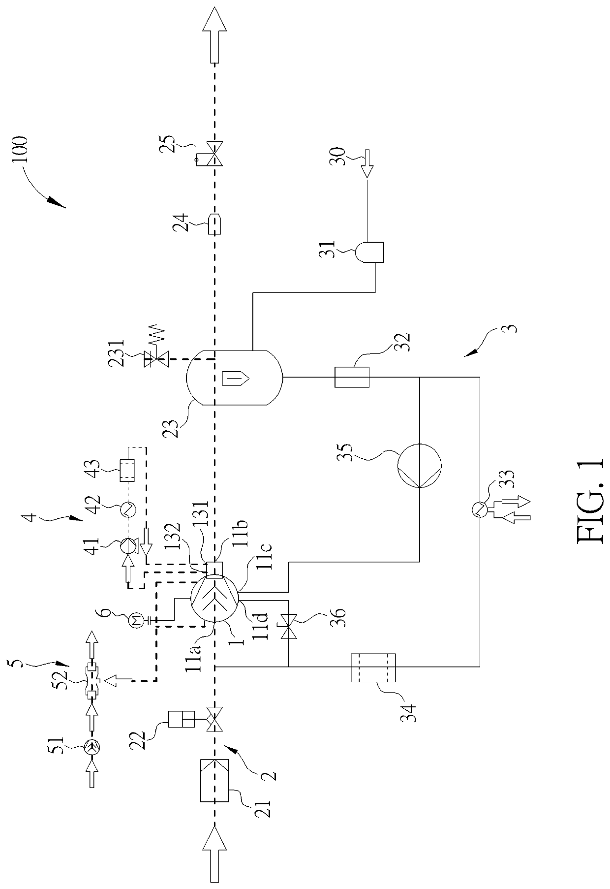
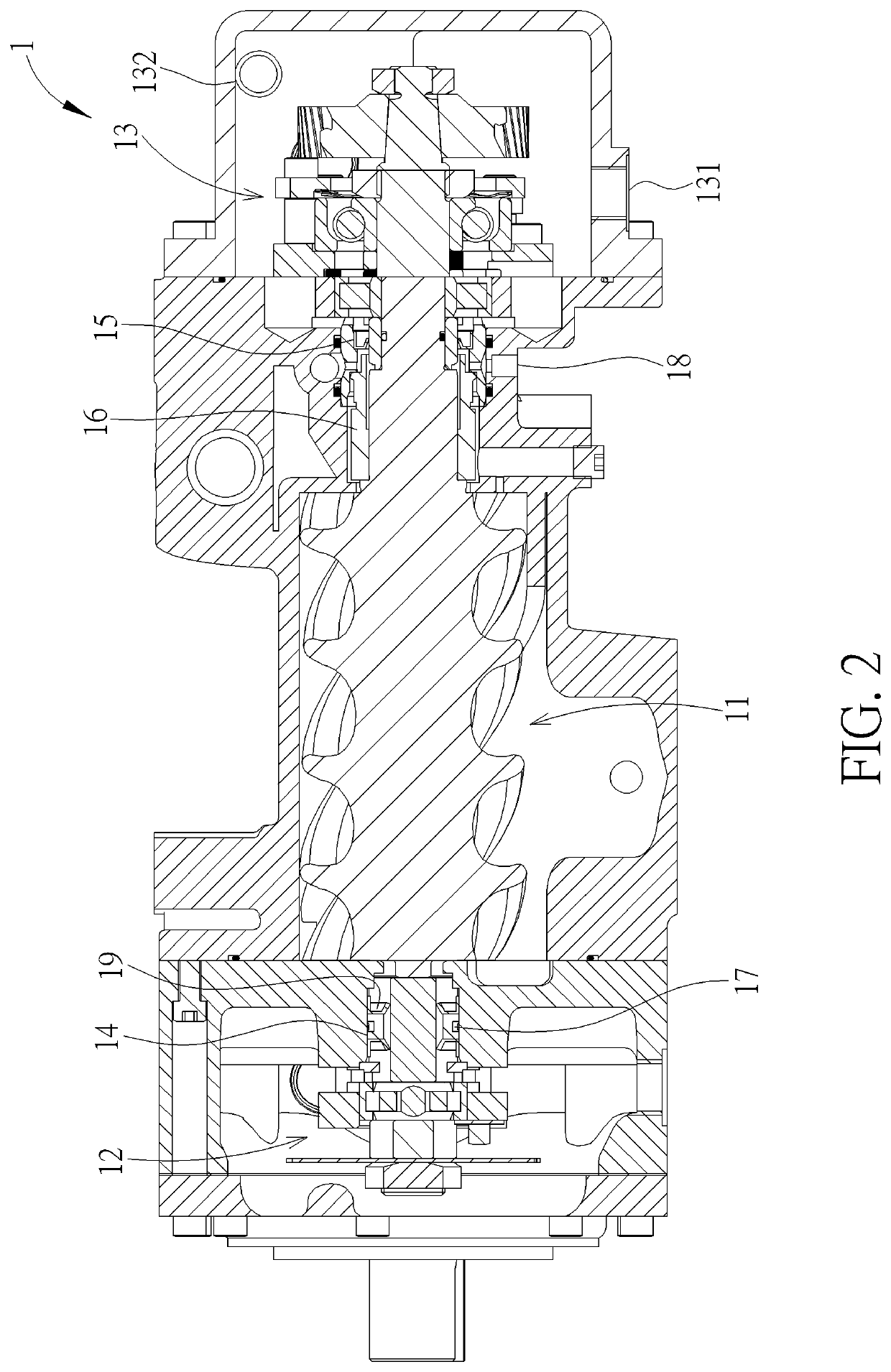
[0020]Please refer to FIG. 1 and FIG. 2. FIG. 1 is a schematic diagram showing an embodiment of the...


PUM

PropertyMeasurementUnit
pressureaaaaaaaaaa
temperatureaaaaaaaaaa
stabilityaaaaaaaaaa

Abstract

A water lubrication air compression system disposes an lubricant heat dissipation system at a bearing chamber close to the high pressure end of the compressor for cooling and circulating lubricant due to the rise of temperature during operation of the compressor, hence enhancing the ability and stability of the compressor. On the other hand, a negative pressure system is connected to the air chambers between the oil lubrication and the water lubrication of the compressor in order to provide a negative pressure. If any leak of water vapor at the compressor chamber or oil vapor at the bearing chamber, the negative pressure system is able to produce a negative pressured condition toward the sealing structure so that the oil lubrication can be effectively isolated from the water lubrication and inter-contamination between the lubricant and water can be avoided.

Description

BACKGROUND OF THE INVENTION1. Field of the Invention[0001]The invention relates to an air compression system, and more particularly, to a water lubrication air compression system.2. Description of the Prior Art[0002]Based on the lubrication properties, a compressor of prior art may be categorized into an oil lubrication compressor and an oil free compressor. The lubricant of the oil lubrication compressor not only effects lubrication and sealing but also forms a lubricant film between the spiral rotors and between the spiral rotors and the compression chamber, where the lubricant film avoids metal surface wearing and leakage of pressurized air and further absorbs heat arising from the compression operation. Thus, a compressor may work with enhanced compression efficiency and lowered working temperature.[0003]After air enters the sealed compression chamber, the lubricant adheres to the spiral rotors and the compression chamber for lubrication and sealing as the compression is activat...

Claims


Application Information

Patent Timeline
Patent Type & Authority Patents(United States)
IPC IPC(8): F01C1/16F04C18/16B01D46/42C02F1/44C02F5/00F04C18/107F04C29/02F04C29/04F03C4/00F03C2/00F04C29/00F04C2/00F04C27/00
CPCF04C29/0007C02F1/441F04C18/16B01D46/4272F04C29/04F04C29/0085F04C29/025F04C18/107F04C29/021C02F5/00F04C27/009F04C29/026F04C2210/147F04C2210/1005F04C29/00
Inventor TSAI, MIN-JENLIN, FENG-YUNGTSENG, CHIH-LUNG
Owner FUSHENG IND CO LTD
Why Eureka
Try Eureka