
Process for manufacturing a coated metal strip of improved appearance

a technology of appearance and coating, which is applied in the direction of coating, metallic material coating process, hot-dipping/immersion process, etc., can solve the problems of detriment to the thickness reduction of the paint system, and achieve good mechanical strength, attractive surface appearance, and good resistance to aggressive chemicals

Active Publication Date: 2020-07-28
ARCELORMITTAL INVESTIGACION Y DESARROLLO SL
View PDF33 Cites 0 Cited by
  • Summary
  • Abstract
  • Description
  • Claims
  • Application Information

AI Technical Summary

Benefits of technology

The process achieves a significant reduction in waviness, enabling the use of thinner paint coats while maintaining a smooth appearance, thus improving productivity and surface quality.

Problems solved by technology

However, at the present time, this thickness reduction of the paint system is always to the detriment of the final appearance of the painted surface of the part and is not implemented in industrial production.

Method used


Image

  • Process for manufacturing a coated metal strip of improved appearance
  • Process for manufacturing a coated metal strip of improved appearance
  • Process for manufacturing a coated metal strip of improved appearance

Examples


Embodiment Construction

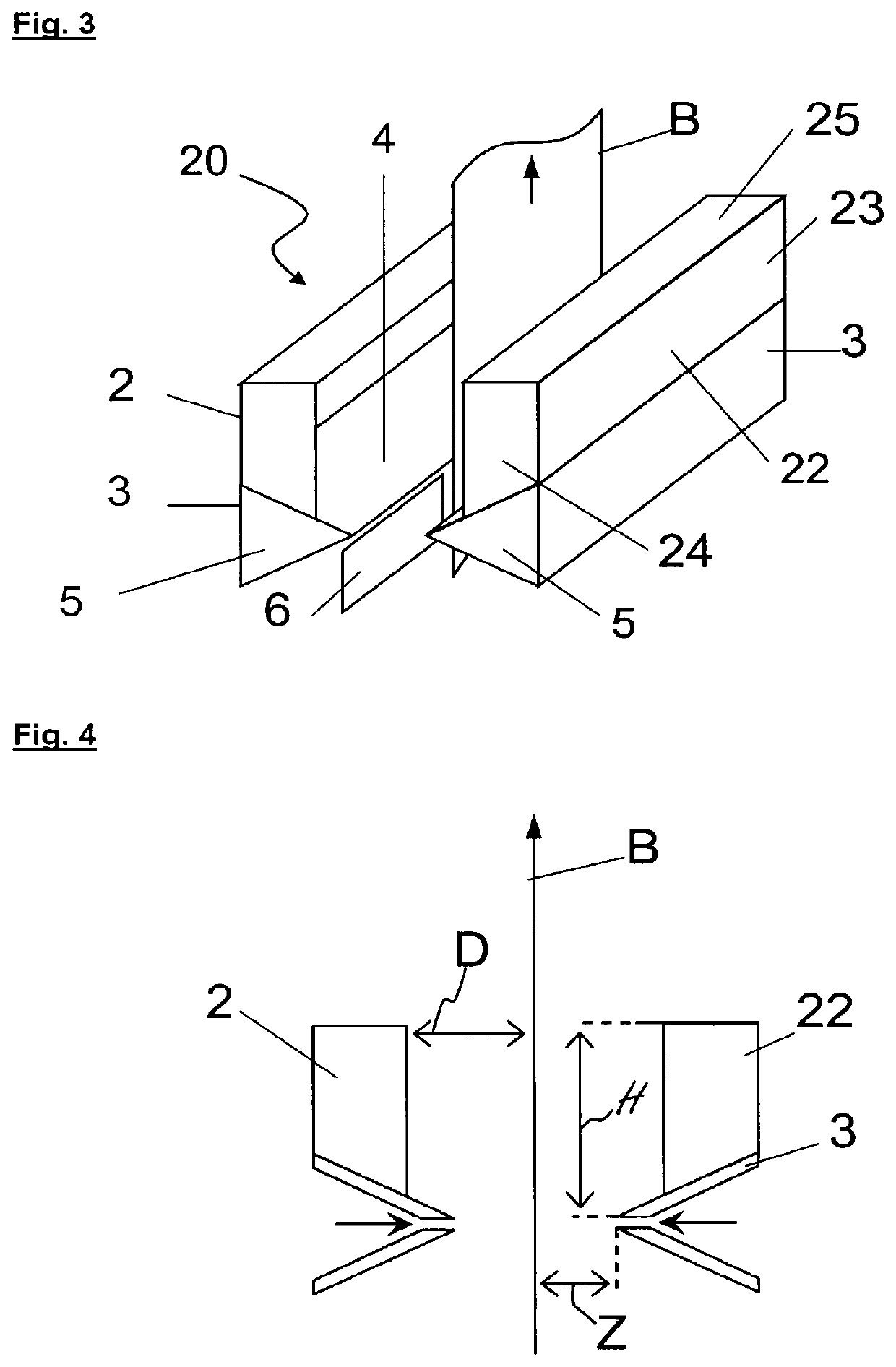
[0108]Referring firstly to FIG. 3, this shows a first embodiment of a confined wiping device 20 according to the invention, which comprises two identical wiping nozzles 3 placed at the same level on each side of the strip B. These wiping nozzles 3 have a triangular general shape and each consist of two longitudinal metal plates 4 and 4′ (not visible) that are fixed together by means of two lateral triangular plates 5 and 5′ (not depicted). The longitudinal metal plates 4 and 4′ are joined together in such a way that thin slots remain between them, so as to allow the pressurized wiping gas, conveyed by means that are not depicted, to pass through it.

[0109]The confined wiping device 20 also includes two confinement boxes 21 and 22 which are each placed on the upper external faces of each nozzle 3, said spaces being formed from upper metal plates 4, and are welded to said plates. The box 22 consists of the assembly of two lateral plates 24 and an upper part consisting of a horizontal p...


PUM

PropertyMeasurementUnit
distanceaaaaaaaaaa
heightaaaaaaaaaa
thicknessaaaaaaaaaa

Abstract

An installation for continuous hot-dip coating of a metal strip is provided. The installation includes a tank containing a bath of molten metal, a metal strip running through the bath and a confined wiping device. The confined wiping device includes at least two wiping nozzles placed on each side of a path of the strip after the strip has left the bath of molten metal. Each nozzle has at least one gas outlet orifice and an upper face. The confined wiping device also includes a confinement box adjacent each upper face. The confinement boxes are open on a face which faces the strip. Each box includes at least one upper part and two lateral parts.

Description

CROSS REFERENCE TO RELATED APPLICATIONS[0001]This is a divisional of U.S. application Ser. No. 13 / 121,833 filed on Aug. 5, 2011 which is a national stage of PCT / FR2010 / 000364 filed on May 11, 2010 which claims priority to PCT / FR2009 / 000562 filed on May 14, 2009, the entire disclosures of which are hereby incorporated by reference herein.[0002]The invention relates to a process for manufacturing a metal strip of improved appearance, more particularly one intended to be used for the manufacture of shell parts for terrestrial motor vehicles, without however being limited thereto.BACKGROUND[0003]Steel sheet intended for the manufacture of parts for a terrestrial motor vehicle is generally coated with a zinc-based metal layer for corrosion protection, deposited either by hot-dip coating in a zinc-based liquid bath or by electrodeposition in an electroplating bath containing zinc ions.[0004]Galvanized sheet intended for the manufacture of shell parts then undergoes a forming operation and...

Claims


Application Information

Patent Timeline
Patent Type & Authority Patents(United States)
IPC IPC(8): C23C2/20C23C2/16C23C2/06
CPCC23C2/06C23C2/20C23C2/16
Inventor DIEZ, LUCMATAIGNE, JEAN-MICHELORSAL, BERTRANDSAINT RAYMOND, HUBERT
Owner ARCELORMITTAL INVESTIGACION Y DESARROLLO SL
Learn More