Methods of charging secondary lithium metal batteries to reactive dead lithium with redox shuttling additives and battery control systems incorporating the same

Active Publication Date: 2020-07-28
SES HLDG PTE LTD
View PDF5 Cites 5 Cited by
  • Summary
  • Abstract
  • Description
  • Claims
  • Application Information

AI Technical Summary

Benefits of technology

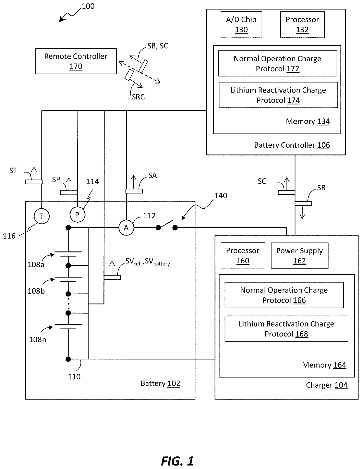
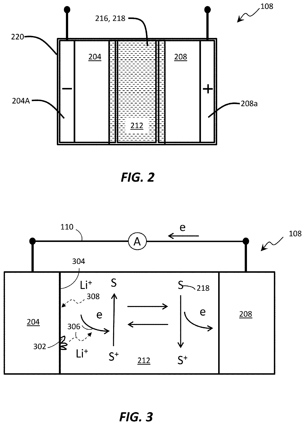
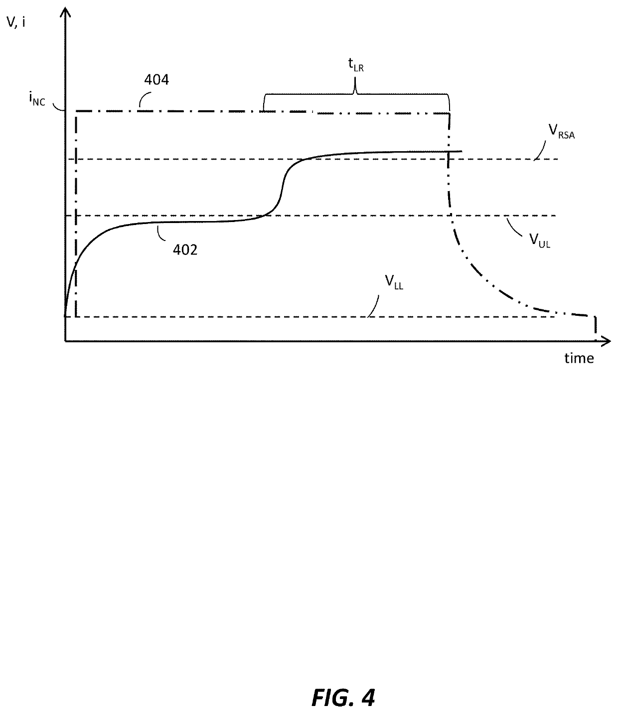
The present patent discusses a method for charging a lithium metal battery using a redox shuttling additive and a lithium metal anode. The method includes initiating a charging process when there is a likelihood of dead lithium on the anode. The charging process involves increasing the potential of the cathode above the normally allowed voltage to oxidize the redox shuttling additive and reactivate the dead lithium with the oxidized redox shuttling additive. This method also includes intentionally overcharging the battery to activate the redox shuttling additive and form shuttling additive cation radicals for reacting with the dead lithium to release lithium ions from the dead lithium. Overall, the method described in this patent enables effective charging of lithium metal batteries.

Problems solved by technology

As the number of charge-discharge cycles increases, an increasing amount of lithium can become “dead lithium” by becoming electrically isolated from the current collector of the anode, thereby making the isolated or dead lithium unavailable for further discharge of energy and reducing the coulombic efficiency of the cell.

Method used


Image

  • Methods of charging secondary lithium metal batteries to reactive dead lithium with redox shuttling additives and battery control systems incorporating the same
  • Methods of charging secondary lithium metal batteries to reactive dead lithium with redox shuttling additives and battery control systems incorporating the same
  • Methods of charging secondary lithium metal batteries to reactive dead lithium with redox shuttling additives and battery control systems incorporating the same

Examples


example 1

nal Lithium Ion Battery Electrolyte

[0048]FIG. 6 illustrates test data from an example test of coin cells using 20 μm thick thin lithium anode and NMC cathode built with 1.2M LiPF6 / EC:EMC=3:7 with or without 0.2M DBBB shuttling additive. The cells were cycled by charging to 4.0V and discharged to 2.5V under 0.1 C rate. As indicated in FIG. 6, cells without DBBB additive exhibited 7 cycles with stable delivered capacities before showing the significant drop on delivered capacities (discharge capacity curves 602). While cells with DBBB additive delivered slightly lower capacities during cycling due to the DBBB shuttling additive activation (100% overcharge control) at ˜3.9V, but with ˜23-25 cycles stable capacities delivery before the dropping of the delivered capacities in the later cycles (discharge capacity curves 604). The average lithium cycling coulombic efficiency per cycle is estimated to be improved from ˜77% for the control cells to 90.5% for the testing cells with DBBB addit...

example 2

entration Electrolyte for Li Metal Anode

[0049]To demonstrate the impact of a shuttling additive on the stability of a lithium metal rechargeable cell system, the same coin cells as in Example 1 were built using a 2M LiFSI / FEC:EMC=2:8 electrolyte that provides more stable lithium metal cycling, either without the DBBB additive (control 2 (702), control 4 (704)) or with 0.2M DBBB additive (DBBB-2 (706), DBBB-3 (708)). The cells were charged at 0.2 C rate to 3.9V and discharged at 1.0 C rate to 2.5V. Due to the presence of DBBB, the testing group cells 706, 708 were partially overcharged at each cycle before reaching 3.9V due to the DBBB activation at around 3.85V in this electrolyte. The charging capacity and discharging capacity are shown in FIGS. 7 and 8, respectively. Although the charging capacities for cells 706, 708 with DBBB additive in the initial 100 cycles are much higher than the control cells 702, 704 (FIG. 7), the actual stored capacity is lower, as represented by the low...


PUM


Abstract

Aspects of the present disclosure include methods of charging secondary lithium metal batteries that include selectively and intentionally overcharging the battery to activate redox shuttling additives in order to reactivate dead lithium. Aspects of the present disclosure also include control systems for determining when to initiate a lithium reactivation charging process and for determining one or more parameters of a lithium reactivation charging protocol.

Description

RELATED APPLICATION DATA[0001]This application claims the benefit of priority of U.S. Provisional Patent Application Ser. No. 62 / 832,974, filed Apr. 12, 2019, and titled, “Method of Using Electrolyte Redox Shuttling Additives to Reactivate the Dead Lithium in Rechargeable Lithium Metal Anode Batteries,” which is incorporated by reference herein in its entirety.FIELD OF THE INVENTION[0002]The present invention generally relates to the field of battery control systems for secondary lithium metal batteries. In particular, the present invention is directed to methods of charging secondary lithium metal batteries to reactivate electrically isolated dead lithium and battery control systems for performing the same.BACKGROUND[0003]Secondary (also referred to as rechargeable) lithium metal batteries provide great promise for the next generation of energy storage devices due to the significantly higher energy density they provide. Unlike conventional lithium ion batteries, which contain anode...

Claims


Application Information

Patent Timeline
IPC IPC(8): H01M10/44H01M10/42H01M10/052H02J7/00
CPCH01M10/4235H02J7/0013H01M10/052H01M10/44H01M10/4242H01M10/0567H01M10/0525H01M10/48Y02E60/10H01M4/382H01M4/628H02J7/00714H02J7/00719H02J7/007194H02J7/0069H02J7/0071
Inventor GAN, HONGKING, MACKENZIEHU, QICHAO
Owner SES HLDG PTE LTD
Why Eureka
Try Eureka