Continuous flow deposition system

a deposition system and continuous flow technology, applied in the direction of lighting and heating apparatus, charge manipulation, furniture, etc., can solve the problems of poor film uniformity and shadowing effects in three-dimensional features, and poor step coverag

Inactive Publication Date: 2005-12-06
VEECON INSTR
View PDF30 Cites 363 Cited by
  • Summary
  • Abstract
  • Description
  • Claims
  • Application Information

AI Technical Summary

Problems solved by technology

Non-uniform gas flow adjacent to the substrate can result in poor film uniformity and shadowing effects in three-dimensional ...

Method used


Image

  • Continuous flow deposition system
  • Continuous flow deposition system
  • Continuous flow deposition system

Examples


Embodiment Construction

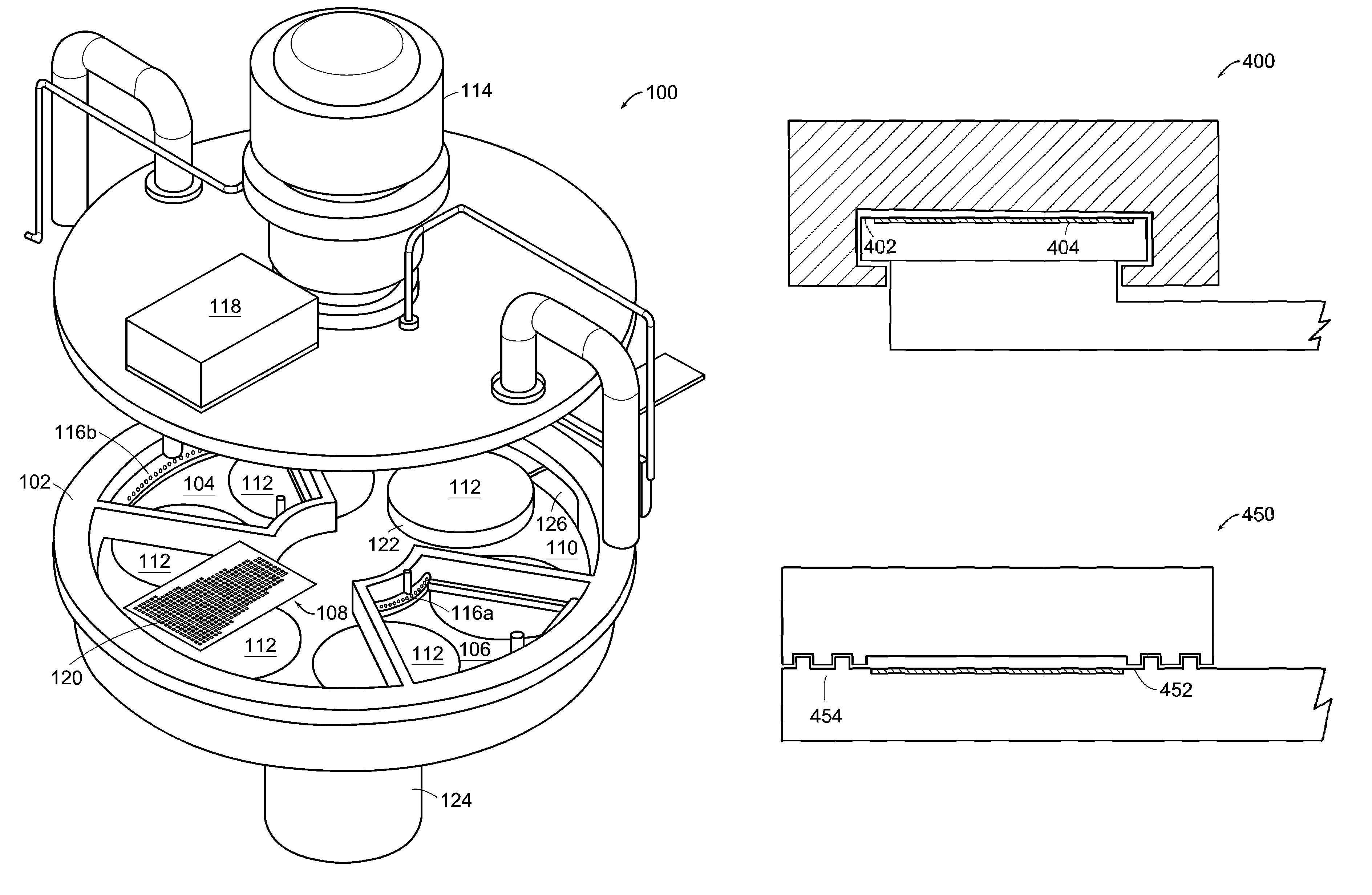
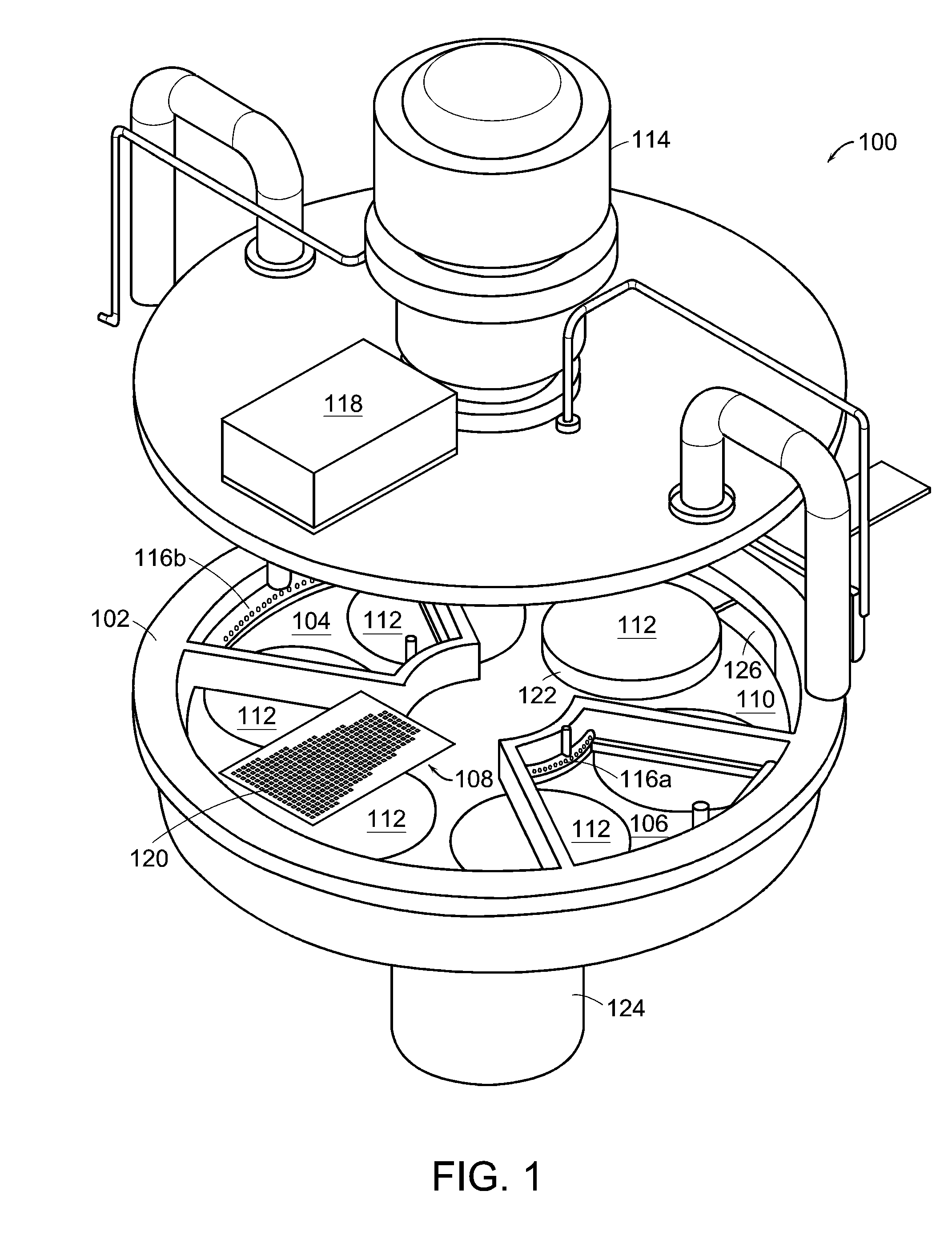
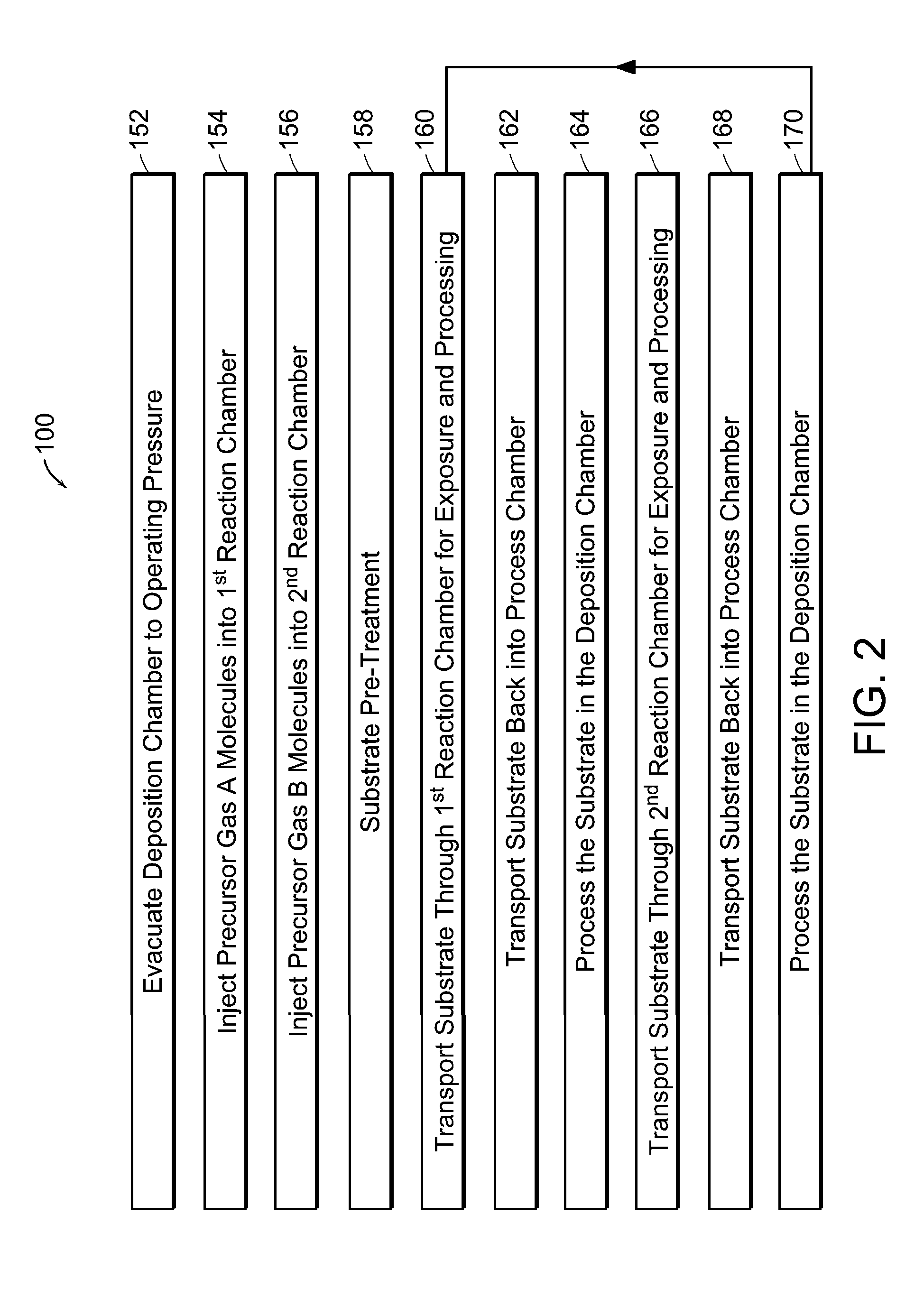
[0015]Atomic Layer Deposition (ALD) is a variation of CVD that uses a self-limiting reaction. The term “self-limiting reaction” is defined herein to mean a reaction that limits itself in some way. For example, a self-limiting reaction can limit itself by terminating after a reactant is completely consumed by the reaction. One method of ALD sequentially injects a pulse of one type of precursor gas into a reaction chamber. After a predetermined time, another pulse of a different type of precursor gas is injected into the reaction chamber to form a monolayer of the desired material. This method is repeated until a film having the desired thickness is deposited onto the surface of the substrate.

[0016]For example, ALD can be performed by sequentially combining precursor gas A and precursor gas B in a process chamber. In a first step, a gas source injects a pulse of precursor gas A molecules into the process chamber. After a short exposure time, a monolayer of precursor gas A molecules de...


PUM

PropertyMeasurementUnit
Partial pressureaaaaaaaaaa
Pressureaaaaaaaaaa
Flow rateaaaaaaaaaa

Abstract

An atomic layer deposition system is described that includes a deposition chamber. A first and second reaction chamber are positioned in the deposition chamber and contain a first and a second reactant species, respectively. A monolayer of the first reactant species is deposited on a substrate passing through the first reaction chamber. A monolayer of the second reactant species is deposited on a substrate passing through the second reaction chamber. A transport mechanism transports a substrate in a path through the first reaction chamber and through the second reaction chamber, thereby depositing a film on the substrate by atomic layer deposition. The shape of the first and the second reaction chambers are chosen to achieve a constant exposure of the substrate to reactant species when the transport mechanism transports the substrate in the path through the respective reaction chambers at the constant transport rate.

Description

CROSS REFERENCE TO RELATED APPLICATIONS[0001]This patent application claims priority to U.S. provisional patent application Ser. No. 60 / 320,065, filed on Mar. 28, 2003, the entire disclosure of which is incorporated herein by reference.BACKGROUND OF INVENTION[0002]Chemical Vapor Deposition (CVD) is widely used to deposit dielectrics and metallic thin films. There are many techniques for performing CVD. For example, CVD can be preformed by introducing two or more precursor molecules in the gas phase (i.e., precursor gas A molecule and precursor gas B molecule) into a process chamber containing a substrate or work piece at pressures varying from less than 10−3 Torr to atmosphere.[0003]The reaction of precursor gas molecule A and precursor gas molecule B at a surface of a substrate or work piece is activated or enhanced by adding energy. Energy can be added in many ways. For example, energy can be added by increasing the temperature at the surface and / or by exposing the surface to a pl...

Claims


Application Information

Patent Timeline
IPC IPC(8): C23C16/44C23C16/455C23C16/458
CPCC23C16/45508C23C16/45551C23C16/4584Y10S414/139
Inventor SFERLAZZO, PIERO
Owner VEECON INSTR
Why Eureka
Try Eureka