Coupling and re-radiating system for millimeter-wave antenna

a millimeter-wave antenna and coupling technology, applied in the field of communication devices configured with millimeter-wave antennas, can solve the problems that the commonly-known embedded millimeter-wave antenna arrays are not easily fitted into the form factor or industrial design (id) of communication devices such as “smart phones

Active Publication Date: 2020-07-28
MOTOROLA MOBILITY LLC
View PDF6 Cites 3 Cited by
  • Summary
  • Abstract
  • Description
  • Claims
  • Application Information

AI Technical Summary

Problems solved by technology

Generally-known embedded millimeter-wave antenna arrays are not easily fitted into t...

Method used


Image

  • Coupling and re-radiating system for millimeter-wave antenna
  • Coupling and re-radiating system for millimeter-wave antenna
  • Coupling and re-radiating system for millimeter-wave antenna

Examples


Embodiment Construction

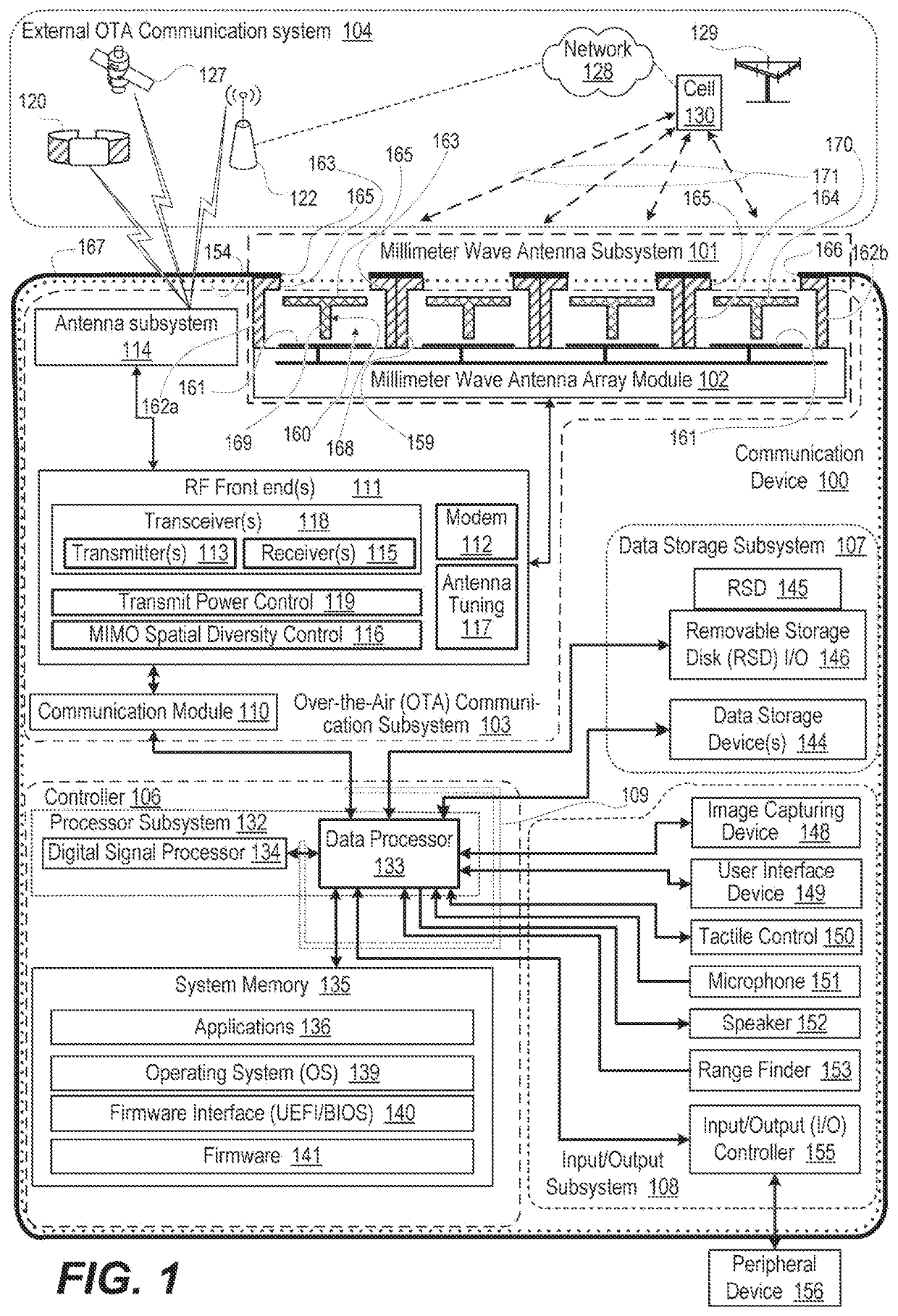
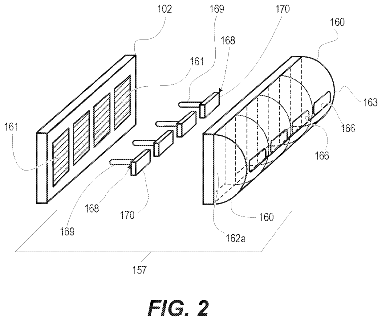
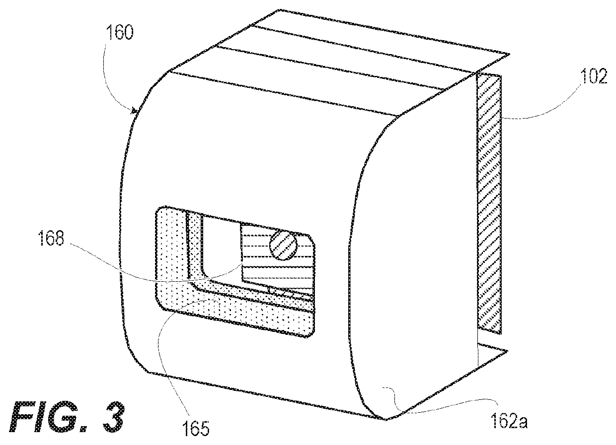
[0011]According to aspects of the present innovation, a communication device, an antenna subsystem, and a method provide a coupling and re-radiating system for embedded millimeter-wave antenna modules. The coupling and re-radiating system achieves wide angle antenna performance within the size constraints of an industrial design (ID) of communication devices such as smart phones. An antenna subsystem of a communication device has a hollowed section, including an inner opening and lateral and outer metallic sides that define a cavity, which is a “below-cutoff cavity”. Since it is imperative to be compact, the size of the cavity is much less than required for cavity mode resonance at a millimeter-wave operating frequency. Thus, a millimeter-wave antenna element located at the inner opening of the cavity only excites an evanescent electromagnetic field in the below-cutoff cavity. A slot antenna is formed in a metallic layer of the outer side of the cavity. A metallic proximity post has...


PUM


Abstract

An antenna subsystem of a communication device has an open cavity including an inner opening and lateral and outer sides that define a cavity. The cavity is sized less than required for cavity mode resonance at a millimeter-wave operating frequency. A millimeter-wave antenna element placed at the inner opening of the hollowed section cavity excites evanescent electromagnetic fields in the cavity. A slot antenna is formed in a metallic layer of the outer side of the cavity. A metallic sectioned proximity post has a first section positioned adjacent to and spaced apart from the millimeter-wave antenna element to couple to, and conduct, the evanescent electromagnetic field. The metallic proximity post has a second section positioned adjacent to and spaced apart from the slot antenna to couple at the millimeter-wave operating frequency, enabling re-radiation by the slot antenna.

Description

BACKGROUND1. Technical Field[0001]The present disclosure relates generally to communication devices and in particular to communication devices configured with millimeter-wave antennas.2. Description of the Related Art[0002]Cellular communications has expanded into multiple communication bands and modulation schemes through the evolution of the telecommunications standard from first generation (1G), second generation (2G), third generation (3G), fourth generation (4G), and recently fifth generation (5G). The 5G cellular systems utilize millimeter-wave bands along with phased array antennas at both the mobile device and base station. Generally-known embedded millimeter-wave antenna arrays are not easily fitted into the form factor, or industrial design (ID), of communication devices such as “smart phones”. The embedded millimeter-wave antenna arrays must be placed on the outside borders of the smart phone in order for the antenna array to radiate. The outer border positioning necessit...

Claims


Application Information

Patent Timeline
IPC IPC(8): H01Q13/18H01Q9/04H01Q1/24
CPCH01Q13/18H01Q9/0407H01Q1/24H01Q1/241H01Q1/521H01Q13/10H01Q21/00H01Q21/0087H01Q1/243H01Q21/08H01Q21/064H01Q9/0457H01Q13/106H01Q3/26
Inventor SAEIDI, CHIYAKRENZ, ERIC L.
Owner MOTOROLA MOBILITY LLC
Why Eureka
Try Eureka