Intraseptal multi-electrode cardiac pacemaker and methods of use thereof
a multi-electrode, cardiac pacemaker technology, applied in the field of cardiac pacing, can solve the problems of difficult implementation, low capture threshold, and deployment of pacing electrode aimed at reaching intended conduction fibers such as his bundle, and achieve the effect of rapid identification of best stimulation sites
- Summary
- Abstract
- Description
- Claims
- Application Information
AI Technical Summary
Benefits of technology
Problems solved by technology
Method used
Image

Examples
first embodiment
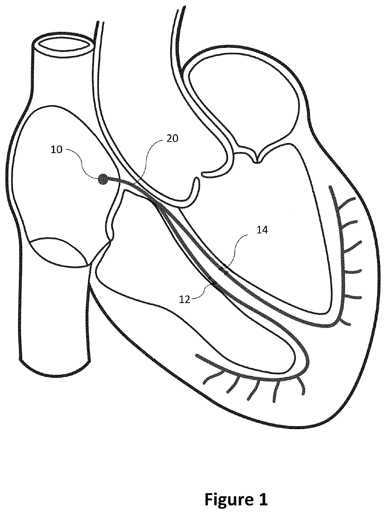
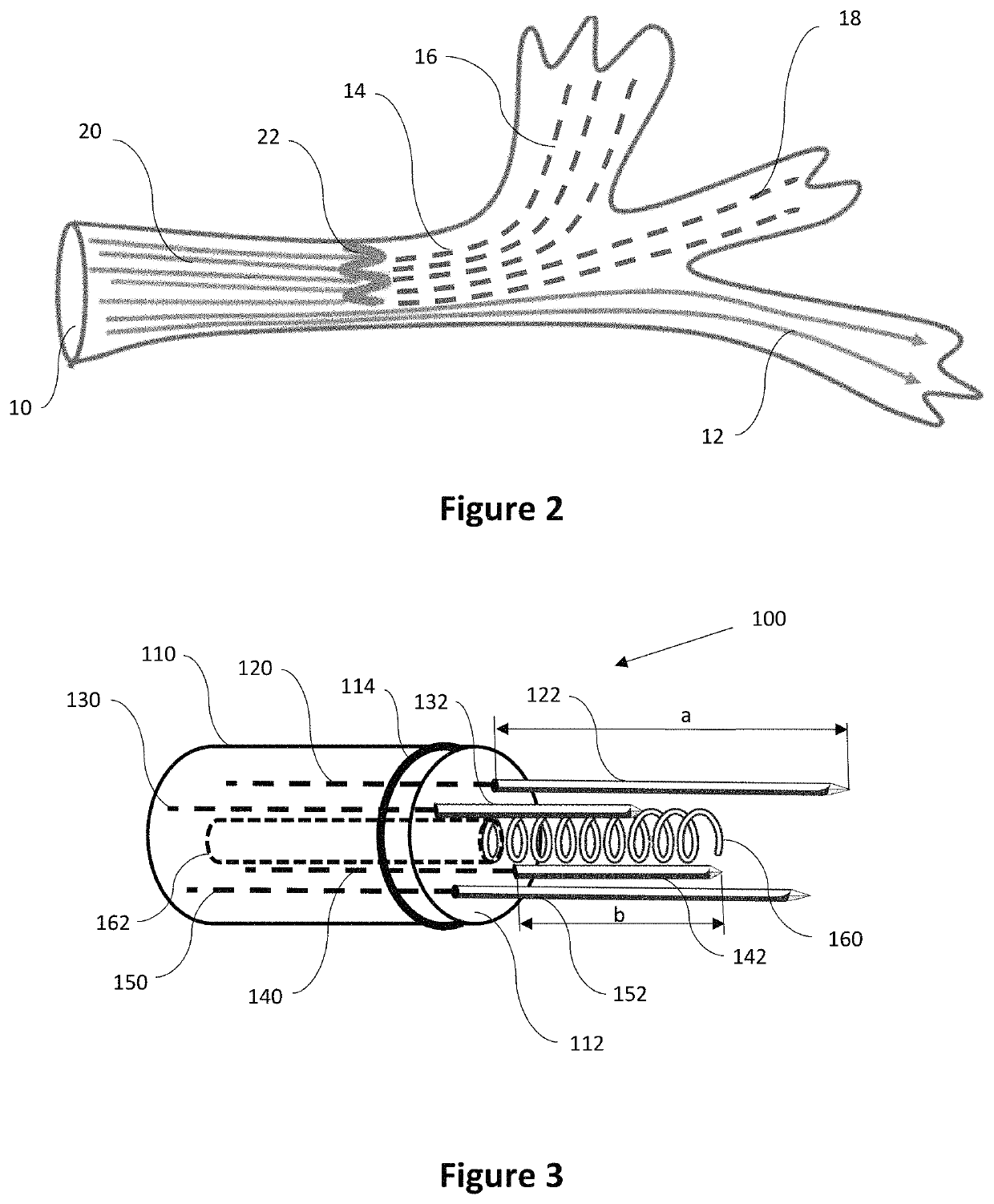
[0044]FIG. 3 shows the intraseptal multi-electrode cardiac pacemaker 100 of the present invention. Shown in FIG. 3 is a distal end 112 of the flexible conduit 110. The proximal end of the flexible conduit 110 is designed to be connected to a pacemaker controller (not shown) located in a subcutaneous clavicle pocket or another subcutaneous location elsewhere in the body as the invention is not limited in this regard. Flexible conduit 110 may be designed to traverse a portion of a blood vessel such as superior or inferior vena cava in order to connect the pacemaker controller located outside the heart to a location inside the heart where individual electrodes may be implanted, such as an interventricular septum.
[0045]The flexible conduit 110 may be configured to house a plurality of first individual electrical wires positioned in parallel to each other and extending inside the conduit—such as electrical wires 120 and 150 seen in FIG. 3. In some embodiments, some or all of the pluralit...
embodiment 200
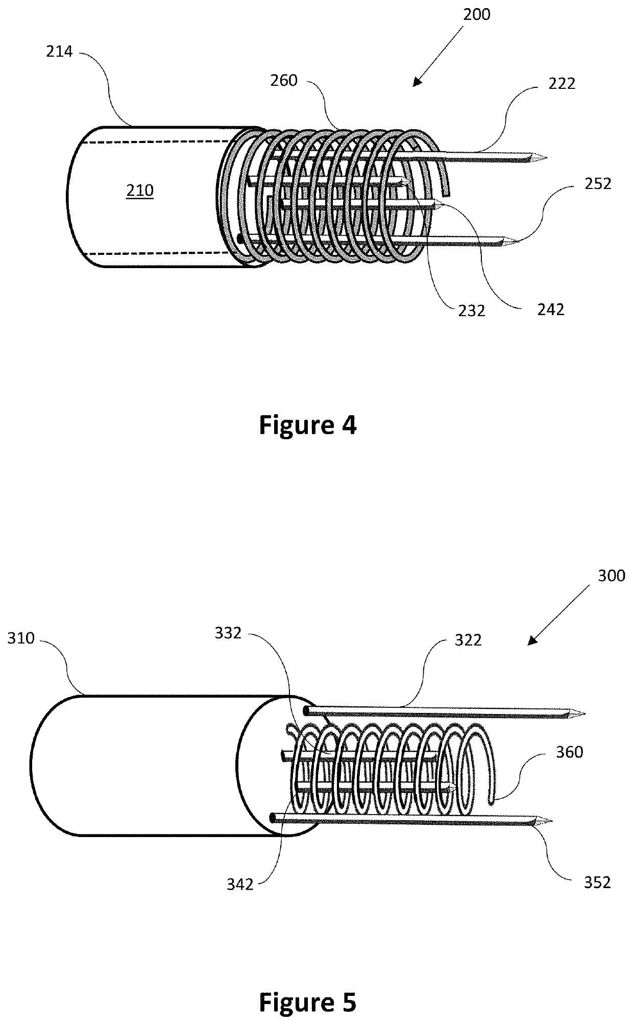
[0058]FIG. 4 shows a flexible conduit 210 of a second broad embodiment 200 of the present invention, in which the tissue attachment screw 260 may have a diameter close to that of the outside diameter of the flexible conduit 210 and all of the first individual electrodes 222 and 252 as well as all second individual electrodes 232 and 242 are positioned inside the tissue attachment screw 260. As described above, this design may also be made in two alternative configurations: (1) one design with the tissue attachment screw 260 fixedly attached to the distal end of the flexible conduit 210 and slidable retractable first and second individual electrodes, and (2) a separately rotatable tissue attachment screw 260 (such as activated by an optional rotatable sleeve 214 placed over flexible conduit 210 and first / second individual electrodes 222, 232, 242, 252 fixedly attached to the flexible conduit 210 and extending therefrom by a respective first or second distance as described above.
[0059...
sixth embodiment
[0063]Flexible conduit 600 according to the present invention is shown in FIG. 8. One or several of the retractable individual electrodes may be pre-formed and configured to extend radially away from the center of the conduit upon implantation. In one example, the plurality of first individual electrodes 622 and 652 may be designed to be similar to that described above and may be fixedly attached to and extend from the distal end of the flexible conduit 610. At the same time, three of the second individual electrodes 632, 642, 644 may be preformed so as to expand radially away from the center of the flexible conduit when they are caused to emerge from the body of the flexible conduit upon implantation. The steps of deployment of the flexible conduit 610 in this case may include retraction of second individual electrodes 632, 642, 644 inside the body of the conduit 610; positioning of the distal end of the conduit 610 adjacent the a target implantation site (optionally with a guidewi...
PUM
 Abstract
Description
Claims
Application Information