Inkjet printing apparatus

a printing apparatus and inkjet technology, applied in printing, typewriters, power drive mechanisms, etc., can solve the problems of difficult use of recording mediums with thicknesses w of 1 mm or more, difficult printing of textile printing using thick mediums such as fabrics, and difficult printing with inkjet printing apparatus. achieve the effect of high-resolution printing

Active Publication Date: 2020-08-18
MIMAKI ENG
View PDF6 Cites 0 Cited by
  • Summary
  • Abstract
  • Description
  • Claims
  • Application Information

AI Technical Summary

Benefits of technology

[0017]This disclosure provides a plurality of printing modes. One of the printing modes is in charge of high-speed, high-resolution printing of the known art, and the other printing modes are in charge of printing control with a greater head gap and a lower main scanning speed not to lose sharpness of a print result. In one of the other printing modes, an ink droplet flying space between a head unit and a recording medium is supplied with any gas but air, for example, helium gas. By having these printing modes selectively switched to one another, high resolution, high printing speed, and large head gap are all feasible in one inkjet printing apparatus.
[0038]2) The inkjet printing apparatus may enable high-resolution printing even with head gaps 10 times greater than in the conventional printers. Print mediums that can be handled by such an inkjet printing apparatus may include three-dimensional objects with many irregularities.

Problems solved by technology

When the head unit 105 is moving fast during the main scans (see FIG. 5B described later), the movement and resulting vibration of the head unit 105 may undermine desired sharpness of a print result.
Therefore, any recording mediums having thicknesses W of 1 mm or more may be difficult to use.
Therefore, textile printing using thick mediums such as fabric may be often difficult to perform with the inkjet printing apparatus 101.
There are issues, however, with the technique described in Japanese Patent No. 5280073.
One of the issues is that vapor pressure resulting from components of the ejected ink may only allow the pressure reduction to a limited range.
The other issue is that the pressure reduction, if overdone, may finally change properties of the ink.
In any industrial and technical fields that demand higher resolution and precision, transition from analog printing to inkjet printing is rather slow, because digital printers for inkjet printing may have the following issues yet to be addressed.
The inkjet printing, therefore, may be difficult to print lines of 60 μm or less in width.
Another issue to be addressed with the inkjet printing is that such instability of the ink droplet landing positions degrades sharpness of a print result to as low as approximately a fraction of that of an analog print result.
Thus, sharp, high-resolution images may be conventionally difficult to obtain with the inkjet printing.
In case the size, initial speed, and ejection angle of ink droplets are inconstant, therefore, the landing positions may become more variable and more inaccurate under the impact from crosswind that increases with higher printing speeds, and a print result may lose desirable sharpness and resolution.
Typically, textile mediums, such as fabric and woven fabric, are thick and have very uneven surfaces.
Then, a print result may inevitably have poor sharpness.
Thus, the wide-gap printing may be conventionally difficult to print high-resolution, sharp, and clear images at high speeds on mediums with such large irregularities and long-pile fabrics.

Method used


Image

  • Inkjet printing apparatus
  • Inkjet printing apparatus
  • Inkjet printing apparatus

Examples


first embodiment

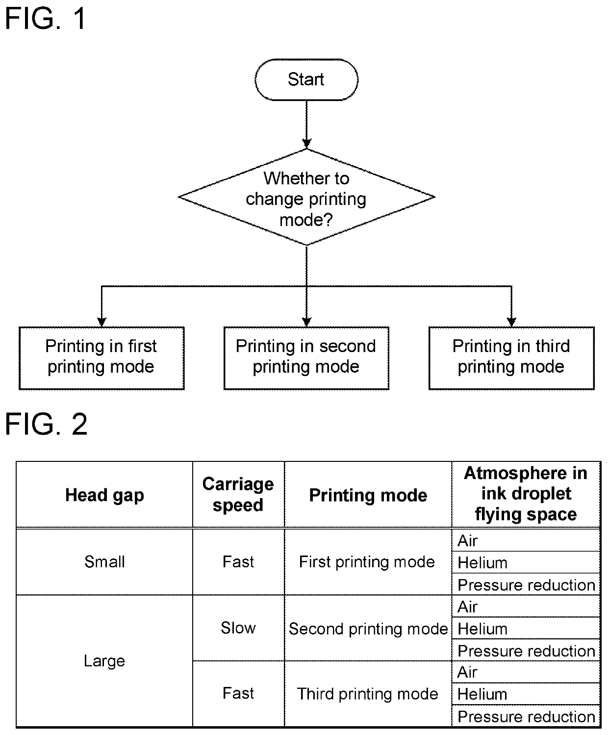
[0050]FIG. 1 is a drawing that illustrates selectable printing modes in an inkjet printing apparatus 1 according to this disclosure. The inkjet printing apparatus 1 has a mode storage (not illustrated in the drawings) in which a plurality of printing modes are storable. The printing mode may be selected by a user manipulating a switch or may be selected by software controlled by a controller 20.

[0051]Examples of the printing modes are given below as three printing modes.

[0052]First Printing Mode

[0053]Regular printing mode (high-speed printing mode): printing mode in which conventional one-pass scans or multi-pass scans are performed.

[0054]Second Printing Mode

[0055]High-resolution and wide-gap printing mode (low-speed printing mode): printing mode in which a scanning speed of a head that moves relative to a medium (recording medium) is decreased to, for example, one-tenth or less or desirably one-hundredth or less of an initial ejection speed VO of ink droplets, or scanning is tempor...

second embodiment

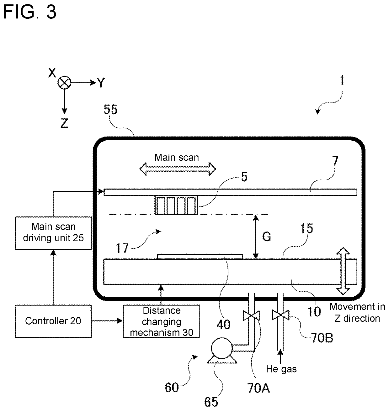
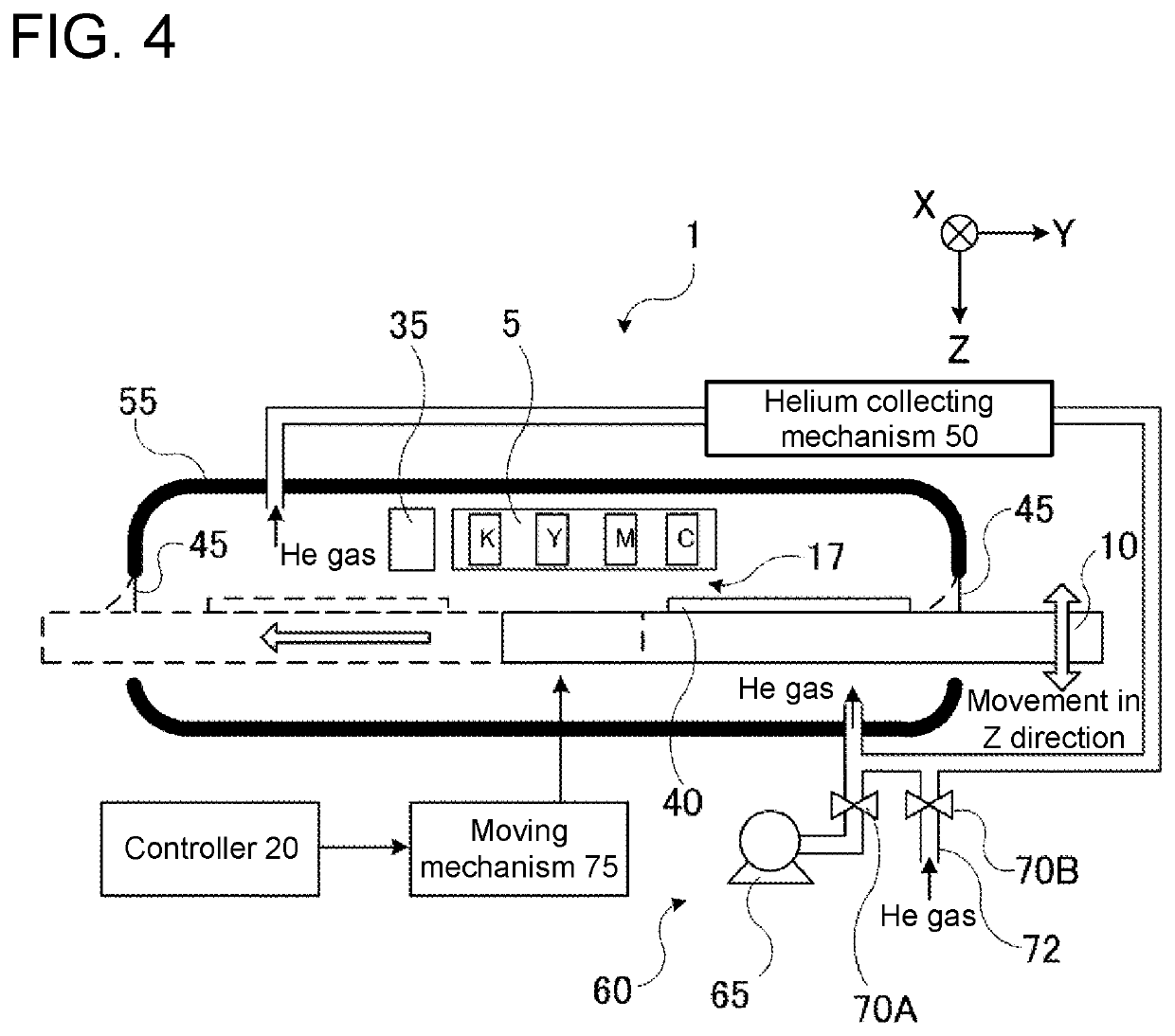
[0086]FIG. 4 is a drawing of an inkjet printing apparatus 1 according to this disclosure. The inkjet printing apparatus 1 includes a head unit 5 from which ink is ejected, a mounting unit 10 having an upper surface to be mounted with a recording medium 40, a moving mechanism 75 that moves the mounting unit 10 in X-Y direction illustrated in FIG. 4 which is horizontal direction, and a distance changing mechanism 30 (not illustrated in the drawing) that changes a relative distance between the head unit 5 and the mounting unit 10 (head gap G). The inkjet printing apparatus 1 includes an isolation chamber 55 that isolates the ink droplet flying space 17 between the head unit 5 and the recording medium 40 from atmospheric air, a moving mechanism 75 that moves the mounting unit 10 in X-Y direction illustrated in the drawing which is horizontal direction, a gas replacement device 60 that replaces gas in the ink droplet flying space 17 of the isolation chamber 55 with helium gas, and a heli...


PUM


Abstract

An inkjet printing apparatus includes a mounting unit where a recording medium is mountable, a head unit that ejects ink droplets to the recording medium, a planar direction driving unit that drives at least one of the head unit ejecting the ink droplets and the mounting unit to move in a planar direction and that changes a relative positions of the head unit and the mounting unit in the planar direction, and a height direction driving unit that changes a relative positions of the head unit and the mounting unit in a height direction perpendicular to the planar direction. The planar direction driving unit has a moving speed changing mechanism that changes a carriage speed between the head unit and the mounting unit in the planar direction. The height direction driving unit has a distance changing mechanism that changes a distance between the head unit and the mounting unit.

Description

CROSS REFERENCE TO RELATED APPLICATIONS[0001]This application claims the priority benefit of Japanese Patent Application No. 2018-025675, filed on Feb. 16, 2018. The entirety of the above-mentioned patent application is hereby incorporated by reference herein and made a part of this specification.TECHNICAL FIELD[0002]This disclosure relates to an inkjet printing apparatus.DESCRIPTION OF THE BACKGROUND ART[0003]Industrial applications of use of inkjet printers include wide format printers for digital textile and sign graphics developed in early stages, and are further expanding in recent years into a broader range of industrial and technical fields, for example, digital printing and digital decoration required to deal with different demands ranging from mass production to individual production (production by order).[0004]Among the conventional analog-based printing applications, transition to digital printing is going well with, especially, POD (print-on-demand) mostly targeted for i...

Claims


Application Information

Patent Timeline
Patent Type & Authority Patents(United States)
IPC IPC(8): B41J25/00B41J25/308B41J29/377B41J11/20B41J19/14B41J3/407B41J19/20
CPCB41J25/001B41J29/377B41J11/20B41J19/145B41J25/308B41J3/4078B41J19/202B41J19/207
Inventor OHNISHI, MASARU
Owner MIMAKI ENG
Why Eureka
Try Eureka