Lightning transmission device between the rotor and the nacelle in a wind turbine

a transmission device and wind turbine technology, applied in the direction of mechanical energy handling, machines/engines, mechanical equipment, etc., can solve the problems of affecting the operation of operators, affecting the operation of the wind turbine, and affecting the inner components of the wind turbin

Active Publication Date: 2020-08-18
GAMESA INNOVATION & TECH SA
View PDF3 Cites 0 Cited by
  • Summary
  • Abstract
  • Description
  • Claims
  • Application Information

AI Technical Summary

Benefits of technology

[0019]In addition, it is described that both platens are coupled directly or indirectly to an electrical insulator, which is also coupled again directly or indirectly to the hub of the relevant wind turbine. Therefore, the electrical insulator ensures the impediment of the current running from the first platen to the hub, preventing impairment of the bearings and other mobile elements of said wind turbine.
[0024]It is seen that the oblong groove of the second platen ensures that the distance between the end of the two platens can be modified, which is directly related to the length of the oblong groove, an easy, versatile solution for each type of installation, and a procedure of installation of the lightning transmission device can be described, which comprises the following stages:
[0047]It is seen that in this second alternative there is permanent contact between the insulating elements and the relevant metal strip of the blade and the gutter; therefore, there can be a wear of said insulating elements requiring more frequent periodic maintenance than in relation to the first alternative; but as advantage over it it is seen that the distance between the ends of the platens and the metal strip of the blade and the gutter is always constant, as it is predefined in stages a) and b) of the associated procedure. On the other hand, as there is no direct contact between the platens and the blade metal strip and the gutter, respectively, no welding points will be produced when running the lightning, which does occur with the systems based on direct contact. Finally, the insulating material is selected to have a high resistance to abrasion and a low friction coefficient, to reduce possible noise and wear.
[0048]Finally, with regard to both alternatives of embodiment, it describes the preferred option wherein the electrical insulator is coupled to the hub of the wind turbine through a base that shows relative displacement means between the electrical insulator and the hub of the wind turbine. It allows a higher flexibility of installation for the purpose of absorbing errors of geometry or installation of the elements adjacent to the lightning transmission device object of the invention.
[0050]Therefore, with the proposed invention a lightning transmission device is obtained which is able to protect the wind turbine from overcurrent in its main entities and caused by atmospheric lightnings that can fall on this wind turbine, thanks to an easy, versatile lightning transmission device that is easy to install for the so diverse conditions existing at the site of each wind turbine and ensures the adequate transmission of the electrical current from the origin to ground safely and effectively.

Problems solved by technology

This location in exposed areas and the itself geometry of wind turbines, which corresponds to a pole anchored on its basis to the ground, and in the upper part has a hub from where leave three or more blades of aerodynamic profile; it makes that the probability of attracting lightning is high and, once the lightning reaches the wind turbine, a high-magnitude current runs through it, that can impair the inner components of the wind turbine, with the subsequent damage for the energy supplying company, and the risk involved for the operators from replacing said impaired parts in position situ according to the extreme locations of the wind turbines.
However, this solution shows the major disadvantage that the lightning discharged by this way damages the bearings and discharge train, so alternative solutions have been searched for.
This solution ensures the non-impairment of the main components of the wind turbine, but shows an inconvenience related mainly to the assembly and installation of said lightning transmission device with respect to the blade and the gutter; as for the lightning transmission onto the ground to be performed optimally, predefined, specific distances must be ensured between the ends of the conductor bar and the blade strip and the gutter, respectively, without direct contact between them; for this, the transmission device must be placed with a lot of precision, as if the distance between the metal strip of the blade and the end of the bar, or between the other end of the bar and the gutter is excessive, the tension required for the electrical arc to be triggered increases between them and can stop working adequately, and the arc will jump to other metal elements close to the wind turbine, with the subsequent problem involved by this.
It must be noted that there are also lightning transmission devices with direct contact between the blade (turning over its shaft and also turning with the hub) and the gutter (static), but these generate welding problems when a high current runs through it, generating excessive noises due to rubbing between components, in addition to requiring frequent maintenance due to wear for the friction between mobile and fixed parts.

Method used


Image

  • Lightning transmission device between the rotor and the nacelle in a wind turbine
  • Lightning transmission device between the rotor and the nacelle in a wind turbine
  • Lightning transmission device between the rotor and the nacelle in a wind turbine

Examples


first embodiment

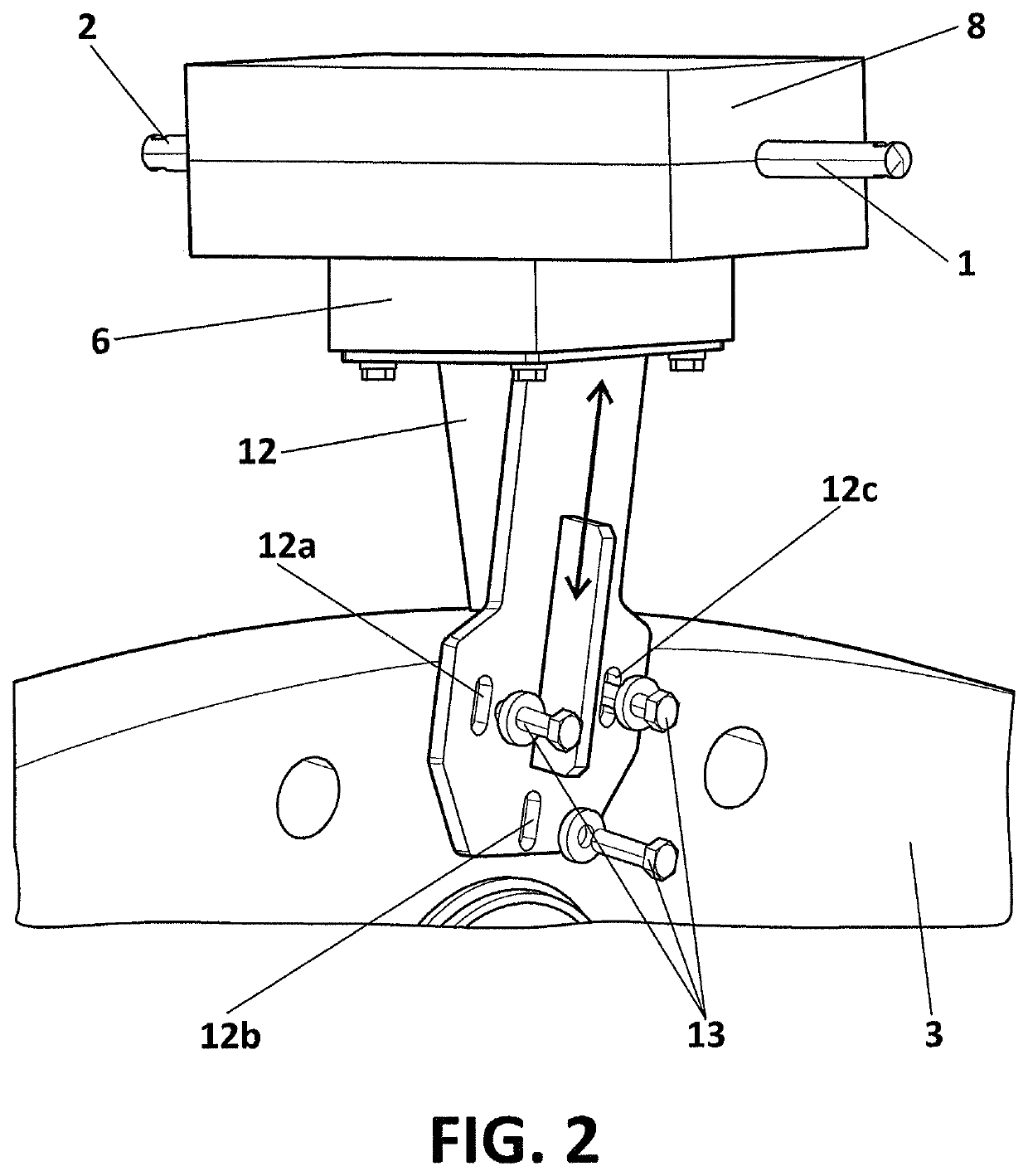
[0021]A) The first embodiment describes the possibility that the relative displacement means between the platens comprise:[0022]An oblong groove belonging to the second platen, and,[0023]at least a hole belonging to the first platen, which is located internally with respect to the projection of the oblong groove of the second platen over the first platen; and wherein at least a fixation is coupled respectively to the groove and the hole, enabling to modify the relative position between the two platens based on the length of said groove.

[0024]It is seen that the oblong groove of the second platen ensures that the distance between the end of the two platens can be modified, which is directly related to the length of the oblong groove, an easy, versatile solution for each type of installation, and a procedure of installation of the lightning transmission device can be described, which comprises the following stages:[0025]a) Positioning the first platen at a given distance from the meta...

second embodiment

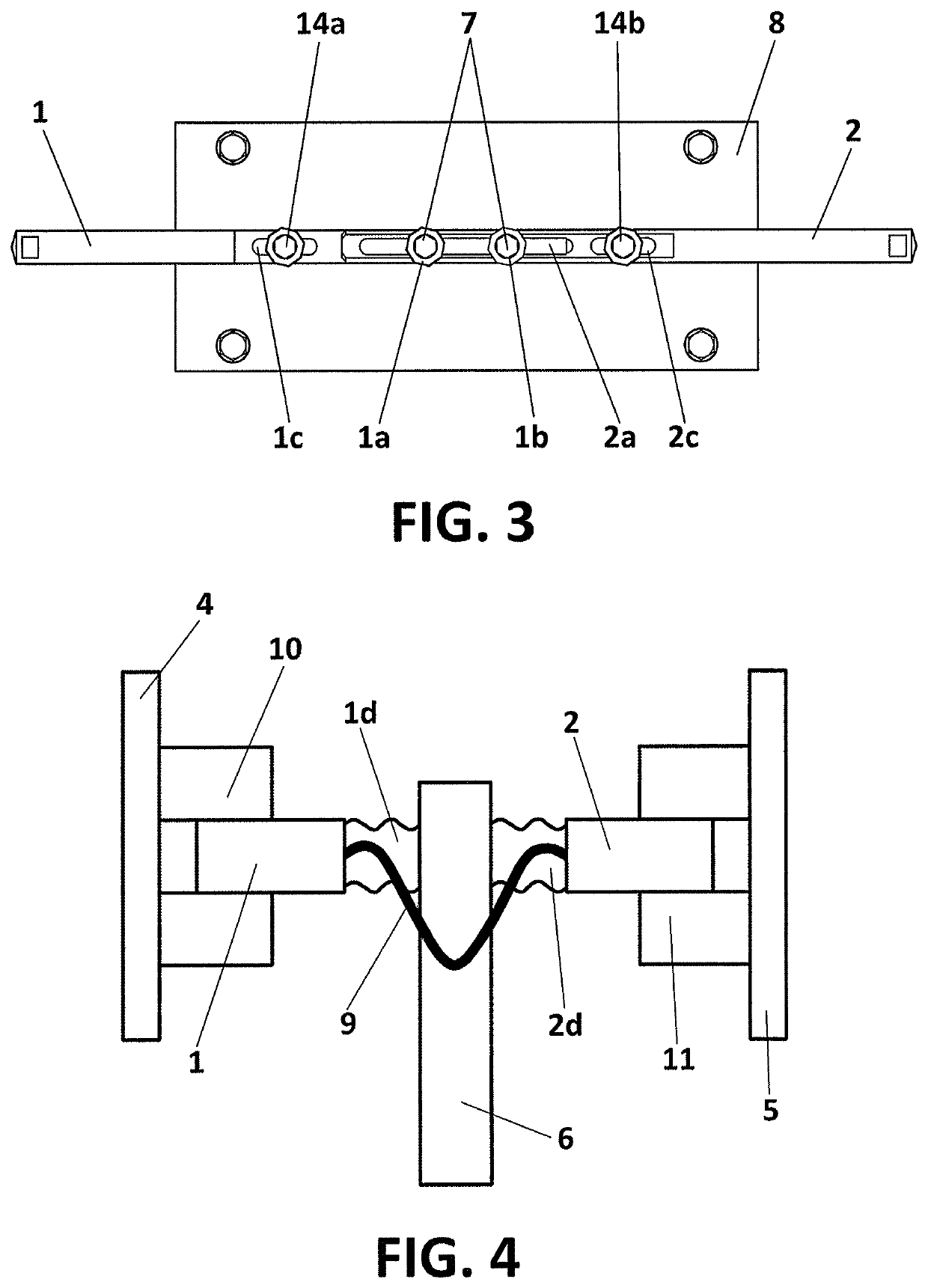
[0034]B) The second embodiment describes the possibility that the relative displacement means between the two platens comprise:[0035]A first elastic spring coupled on one side to the first platen and on the other side to the insulator;[0036]A second elastic spring coupled on one side to the second platen, and on the other side to the insulator;[0037]an electrical conductor wire coupled both to the first platen and to the second platen, and[0038]where in each end of each platen closest to the metal strip and to the gutter, respectively, two insulating elements are positioned, configured to contact in this metal strip and the gutter, respectively, thanks to the elastic strength of both elastic springs; and said insulating elements being configured to avoid contact between the ends of the platens and the metal strip and the gutter element, respectively.

[0039]Significant differences are seen with respect to the first alternative of embodiment of the displacement means, as in this case n...


PUM


Abstract

A lightning transmission device between the rotor and the nacelle in a wind turbine, which comprises: a first electricity conductor platen, where one of its ends is separated at a distance with respect to a metal strip located at a root of each blade; a second electricity conductor platen, where one of the ends is separated a distance with respect to a gutter element; an electrical conductor between the first and second platen; an electrical insulator coupled to said first and second platens; which is also coupled to the hub of the wind turbine; and a relative displacement unit between the first and second platen, the unit configured to ensure a predefined distance between the end of the first platen and the metal strip; and between the end of the second platen and the gutter element.

Description

TECHNICAL FIELD OF THE INVENTION[0001]The present invention relates to a lightning transmission device between the rotor and the nacelle, configured to be installed in a wind turbine, and to the associated installation procedure; which are located in the industry of renewable energies of wind type, as well as in the management and electrical conduction of lightning caused by thunderstorms toward ground.[0002]The lightning transmission device object of invention has as primary aim to protect the sensitive parts of the wind turbine from over-currents in their main entities, which originate through lightning that can fall on said wind turbine, which run part of it to reach ground. This protection is performed thanks to a simple, versatile lightning transmission device, with an optimum installation facility for the so diverse conditions existing in the location of each wind turbine, and that ensures the adequate transmission of electric current, from the rotor of the wind turbine to the...

Claims


Application Information

Patent Timeline
Patent Type & Authority Patents(United States)
IPC IPC(8): F03D80/30H02K7/18
CPCH02K7/1838F03D80/30Y02E10/72F05B2220/32
Inventor AROCENA DE LA RUA, IONAZCONA PEREZ, IGNACIOMORIANA GARCIA, IRUNEMARCH NOMEN, VICTOR
Owner GAMESA INNOVATION & TECH SA
Why Eureka
Try Eureka