Method for the production of a connecting rod

a technology of connecting rods and production methods, which is applied in the direction of mechanical equipment, rotary machine parts, machines/engines, etc., can solve the problems of no longer efficiently heat-treated using conventional methods, and the problem of small connecting rod eyes, so as to avoid premature sintering of powders

Active Publication Date: 2020-08-18
MIBA SINTER AUSTRIA
View PDF10 Cites 0 Cited by
  • Summary
  • Abstract
  • Description
  • Claims
  • Application Information

AI Technical Summary

Benefits of technology

[0010]It is advantageous, in this regard, that shorter drills can be used due to production of the bore from two sides, and therefore the precision of the bore can be improved, since shorter drills have less of a tendency to bend during drilling. Furthermore, in this way the thermal stress on the drill and, above all, on the green compact during drilling can be reduced, since the processing time for production of a partial bore is shorter than the processing time for production of the entire bore. The resulting heat can therefore be better conducted away from the connecting rod shaft.
[0020]In order to protect the green compact during drilling, as much as possible, and to avoid premature sintering of the powder in the region of the drill, it can be provided that a drill is used that has at least one channel in its interior, wherein this channel has an exit opening that is configured in the front end region of the drill.

Problems solved by technology

The production of connecting rods having small connecting rod eyes is problematical, since these can no longer be efficiently heat-treated using conventional methods, for example annealed and / or vapor-treated or plasma-nitrided using known methods.

Method used


Image

  • Method for the production of a connecting rod

Examples


Embodiment Construction

[0025]As an introduction, it should be stated that in the different embodiments described, the same parts are provided with the same reference symbols or the same component designations, wherein the disclosures contained in the description as a whole can be applied analogously to the same parts having the same reference symbol or the same component designations. Also, the position information chosen in the description, such as at the top, at the bottom, on the side, etc., for example, refers to the figure being directly described and shown, and this position information should be transferred analogously to a new position in the case of a change in position.

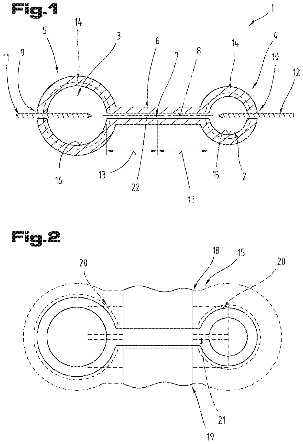
[0026]As was already discussed in the introduction, the invention relates to a method for powder-metallurgical production of a connecting rod 1, as can be seen in FIG. 1. The connecting rod 1 is preferably used in a compressor, which is used, for example, in cooling units, such as refrigerators, for example, or in car air-conditio...


PUM

PropertyMeasurementUnit
diameteraaaaaaaaaa
temperatureaaaaaaaaaa

Abstract

A method produces a connecting rod from a sintered material, which rod has at least one bore having a center axis, and has a first connecting rod eye in a connecting rod head, and a second connecting rod eye in a connecting rod foot, wherein the connecting rod head is connected with the connecting rod foot with a connecting rod shaft, wherein the bore is configured in the connecting rod shaft, wherein furthermore, the connecting rod is produced from a metallic powder, in accordance with a sintering process, for which purpose the powder is pressed into the corresponding mold to form a green compact, the bore is introduced into the green compact, and the green compact is afterward sintered. The bore is introduced into the green compact as a first and second partial bore, proceeding from the connecting rod foot and from the connecting rod head.

Description

CROSS REFERENCE TO RELATED APPLICATIONS[0001]Applicant claims priority under 35 U.S.C. § 119 of Austrian Application No. A 50134 / 2018 filed Feb. 14, 2018, the disclosure of which is incorporated by reference.BACKGROUND OF THE INVENTION1. Field of the Invention[0002]The invention relates to a method for the production of a connecting rod from a sintered material, which rod has at least one bore having a center axis, a first connecting rod eye in a connecting rod head, and a second connecting rod eye in a connecting rod foot, wherein the connecting rod head is connected with the connecting rod foot with a connecting rod shaft, wherein the bore is configured in the connecting rod shaft, wherein furthermore, the connecting rod is produced from a metallic powder, in accordance with a sintering process, for which purpose the powder is pressed into the corresponding mold to form a green compact, the bore is introduced into the green compact, and the green compact is afterward sintered.[000...

Claims


Application Information

Patent Timeline
Patent Type & Authority Patents(United States)
IPC IPC(8): F16C7/02F16C33/14F01M1/06B22F5/10
CPCF01M1/06F16C7/023B22F5/10F16C33/145F16C2204/00B23P2700/04F16C2360/42F16C2220/20B22F2998/10B22F3/02B22F3/162B22F3/10F16C7/02F16C7/00
Inventor NETO, JOSE CORREAPERUGINI, DANIEL AUGUSTO
Owner MIBA SINTER AUSTRIA
Why Eureka
Try Eureka