Measuring device and method for sensing different gases and gas concentrations

a technology of gas concentration and measuring device, which is applied in the direction of measurement device, material analysis through optical means, instruments, etc., can solve the problems of reducing the detection limit of one gas, the radiation intensity at the infrared detector, and the significant disadvantages of its structural size and mechanical susceptibility to vibration and shock

Active Publication Date: 2020-09-08
INFRASOLID GMBH
View PDF32 Cites 1 Cited by
  • Summary
  • Abstract
  • Description
  • Claims
  • Application Information

AI Technical Summary

Benefits of technology

[0055]The offset is generated in that the narrow bandpass interference filter in front of a reference detector transmits a larger spectral range and the reference detector detects a range outside the gas absorption band. Spectral changes which result, for example, due to deposits in the optical measuring channel or due to ambient temperature influences and also intensity drifts and spectral changes of the radiation source can thus be compensated for.
[0056]It is advantageous if the narrow bandpass interference filter in front of a reference detector transmits at least 30% of a wavelength range which is located outside the absorption band of the gas to be measured. This range can also be smaller or larger than 30%, however. It has to be ensured at least that the reference radiation detector detects a larger spectral range than the radiation detector, specifically with a spectral radiation component which is located outside the absorption band of the gas to be detected.

Problems solved by technology

This NDIR gas sensor, which is known as a photoacoustic gas measuring cell, has the significant disadvantages of its structural size and the mechanical susceptibility to vibrations and shocks.
However, the required allocation of the radiation flux emitted by the radiation source onto the two infrared detectors is disadvantageous, whereby the radiation intensity at the infrared detector and thus the detection limit of the gas sensor are reduced. FIG. 2 shows the two-frequency method according to the prior art and the required allocation of the radiation emitted by the radiation source S onto the detectors D1 and D2.
However, only one gas can be measured using the above-mentioned measuring methods and measuring devices suitable for this purpose.
Significant disadvantages of such NDIR gas sensors having multispectral detectors are a constant absorption path or cuvette length for all spectral channels and the distribution of the radiation intensity onto the individual detector elements.
The allocation of the emitted radiation flux onto a plurality of radiation detectors remains a significant disadvantage of this arrangement, whereby only a very small fraction of the radiation intensity arrives at the detectors and the detection limit of the gas sensor device is greatly reduced.
However, a substantial disadvantage therein is also that only a fraction of the measurement radiation is always incident on the detectors, which is moreover dependent on the respective reflection on the measuring chamber wall.
However, this can only take place sequentially.
A simultaneous sensing of the concentration of different gases in a gas mixture is not possible.
Moreover, the absorption path length for every gas is equal and the arrangement may only be miniaturized poorly.

Method used


Image

  • Measuring device and method for sensing different gases and gas concentrations
  • Measuring device and method for sensing different gases and gas concentrations
  • Measuring device and method for sensing different gases and gas concentrations

Examples


Embodiment Construction

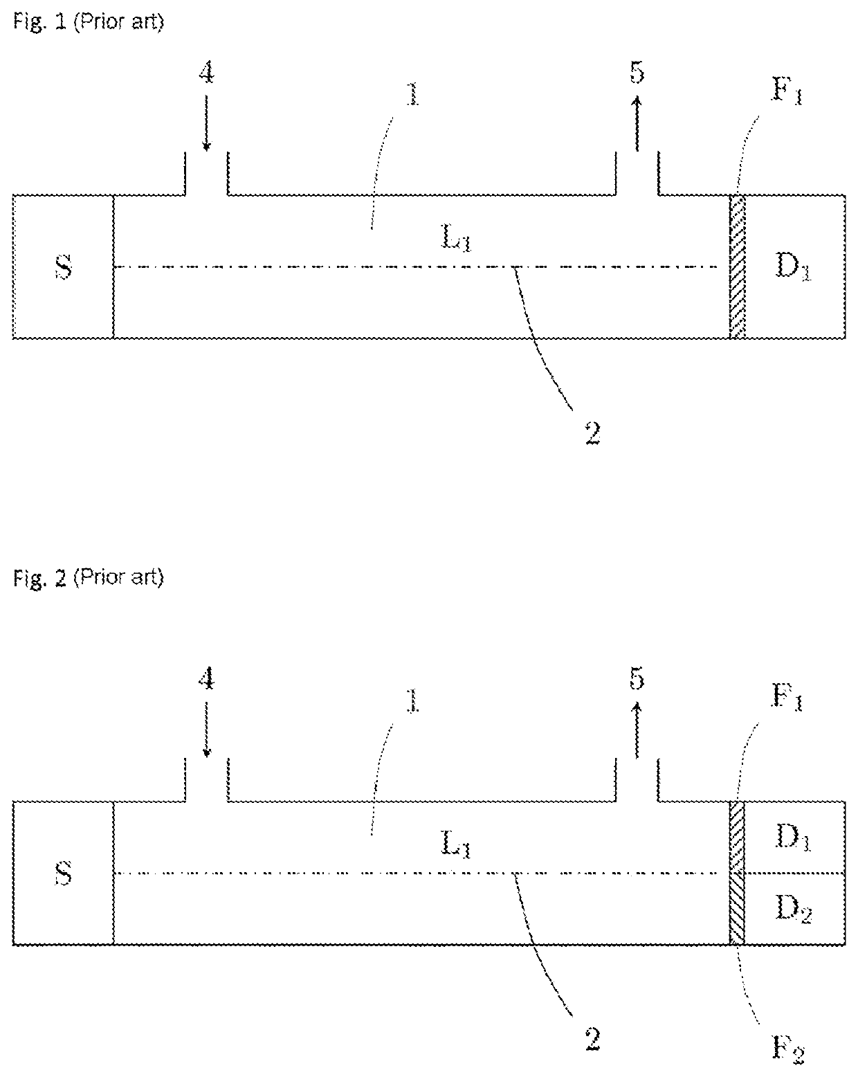
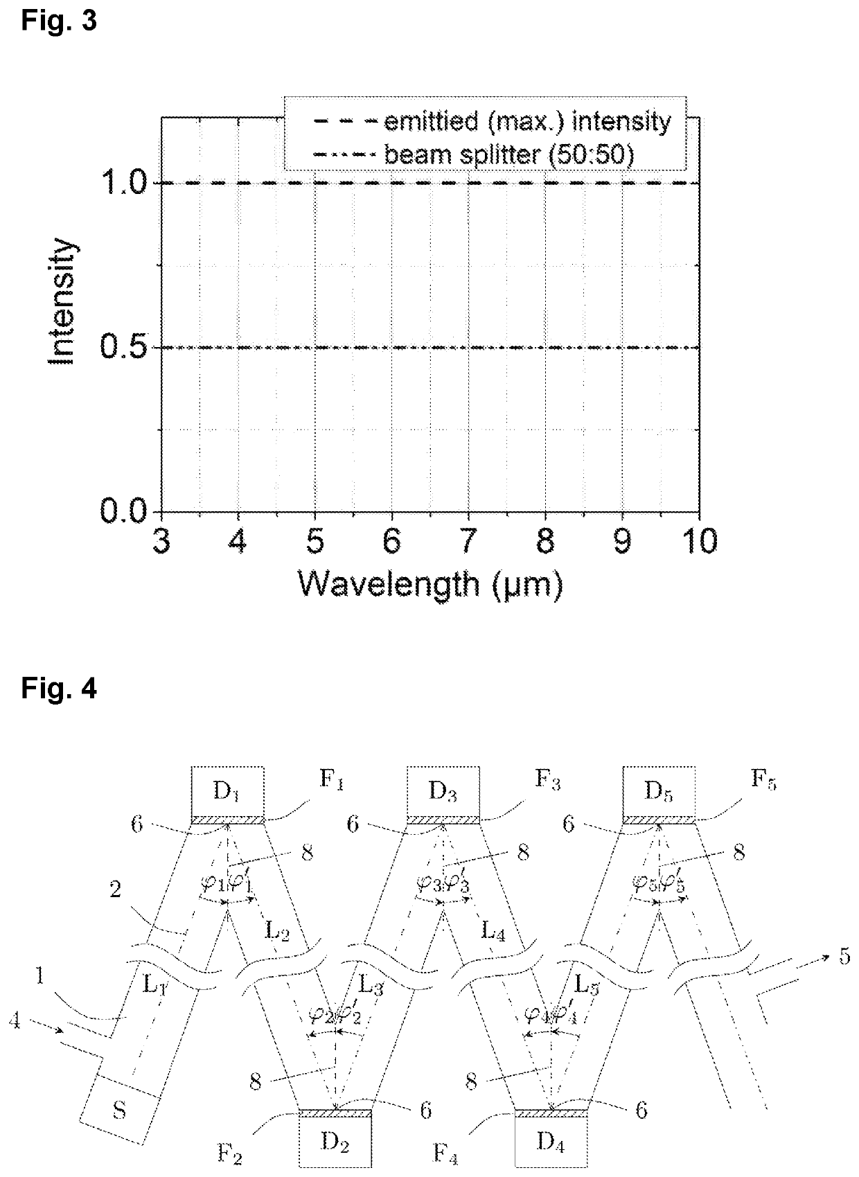
lass="d_n">[0072]FIG. 4 schematically shows a possible embodiment of the measuring device according to the invention. A gas is introduced by laminar flow into the measuring channel 1 via a gas inlet 4. However, the gas can also be introduced over the entire length of the optical path into the measuring channel. The gas inlet can also be designed as a gas-permeable membrane, where the gas diffuses spontaneously into the measuring channel 1. The IR radiation source S emits a beam bundle having a continuous spectrum, which is guided, for example, in a waveguide, the measuring channel 1, in which the gas or gas mixture is located, along an optical path 2 and is incident after an individually settable path length L1 on a narrow bandpass interference filter F1 at the angle φ1. The location of the filter defines a first deflection point 6 of the measuring radiation and only permits a specific wavelength or a very narrow wavelength band of the radiation through and reflects the remainder at...


PUM

PropertyMeasurementUnit
angle φNaaaaaaaaaa
angle φNaaaaaaaaaa
angle φNaaaaaaaaaa

Abstract

A measuring device for sensing different gases and gas concentrations, includes an infrared radiation source, a measurement channel, which has an optical path and a gas interaction path, and radiation detectors arranged along the measurement channel. The optical path has a first band-pass interference filter arranged at a first deflection point and a first radiation detector is arranged after the band-pass interference filter. A method that uses the measuring device, includes: measurement radiation is introduced into the measurement channel containing the gas to be measured, the measurement radiation hits the first band-pass interference filter, wherein only radiation of a wavelength defined by the first band-pass interference filter hits the first radiation detector, radiation reflected at the band-pass interference filter is forwarded along the optical path in the measurement channel to a second radiation detector, and the gas concentrations measured by the radiation detectors are evaluated.

Description

CROSS REFERENCE TO RELATED APPLICATIONS[0001]This application is the National Phase filing under 35 U.S.C. § 371 of International Application No.: PCT / EP2017 / 061059, filed on May 9, 2017, and published on Nov. 16, 2017 as WO 2017 / 194540 A1, and claims priority to German Application No.: 10 2016 108 544.8, filed on May 9, 2016, and to German Application No.: 10 2016 108 545.6, filed on May 9, 2016. The contents of each of the prior applications are hereby incorporated by reference herein in their entirety.BACKGROUND ART[0002]The invention relates to a measuring device for sensing different gases and gas concentrations, which comprises a radiation source, a measuring channel having an optical path and a gas interaction path, and radiation detectors arranged along the measuring channel.[0003]The invention also relates to a method for measuring gases and gas concentrations which uses the measuring device according to the invention.[0004]There are two basic types of gas sensors: interact...

Claims


Application Information

Patent Timeline
Patent Type & Authority Patents(United States)
IPC IPC(8): G01N21/3504G01N21/03
CPCG01N21/031G01N21/3504G01N2201/06113
Inventor SCHOSSIG, MARCONORKUS, VOLKMAROTT, TOBIAS
Owner INFRASOLID GMBH
Why Eureka
Try Eureka