Discrete wavelength tunable laser

a tunable laser and discrete wavelength technology, applied in the field of discrete wavelength tunable lasers, can solve the problems of unable to make tunable lasers made entirely on semiconductor chips without gratings requiring dacs for control, high cost and power consumption, etc., and achieve the effects of reducing increasing the reflectivity of dbrs, and large spectral rang

Active Publication Date: 2019-02-14
ROCKLEY PHOTONICS LTD
View PDF6 Cites 0 Cited by
  • Summary
  • Abstract
  • Description
  • Claims
  • Application Information

AI Technical Summary

Benefits of technology

[0027]It is also envisaged that the tunable DBRs (which may take the form of DS-DBRs) could be adapted to compensate for the spectral profile of the gain medium. The gain element will have a large spectral range over which the power of light generated will depend upon the wavelength. Usually there will be less power at the two extremes of the spectral range, creating a “drop off” in power at the edges of the range. The DBRs could be adapted to compensate for such drops in gain. For example, the reflectivity of the DBR could be reduced at parts of the DBR which correspond to high-gain regions of the spectral profile of the gain medium. Alternatively, or in addition, the reflectivity of DBRs could be increased at sections configured to reflect wavelengths which correspond to spectral regions of low-gain from the gain medium.

Problems solved by technology

Unfortunately, the requirement for full range continuous tunability results in expensive and power-hungry electronic circuitry, most particularly due to the requirement for digital-analog conversion (DAC) chips.
However, tunable lasers made entirely on semiconductor chips have been impossible without gratings requiring DACs for control.
The challenge of this patent application is to create tunable lasers based upon the DS-DBR design principle but with cheaper and lower power consuming control electronics, in particular not requiring DACs.

Method used


Image

  • Discrete wavelength tunable laser
  • Discrete wavelength tunable laser
  • Discrete wavelength tunable laser

Examples


Embodiment Construction

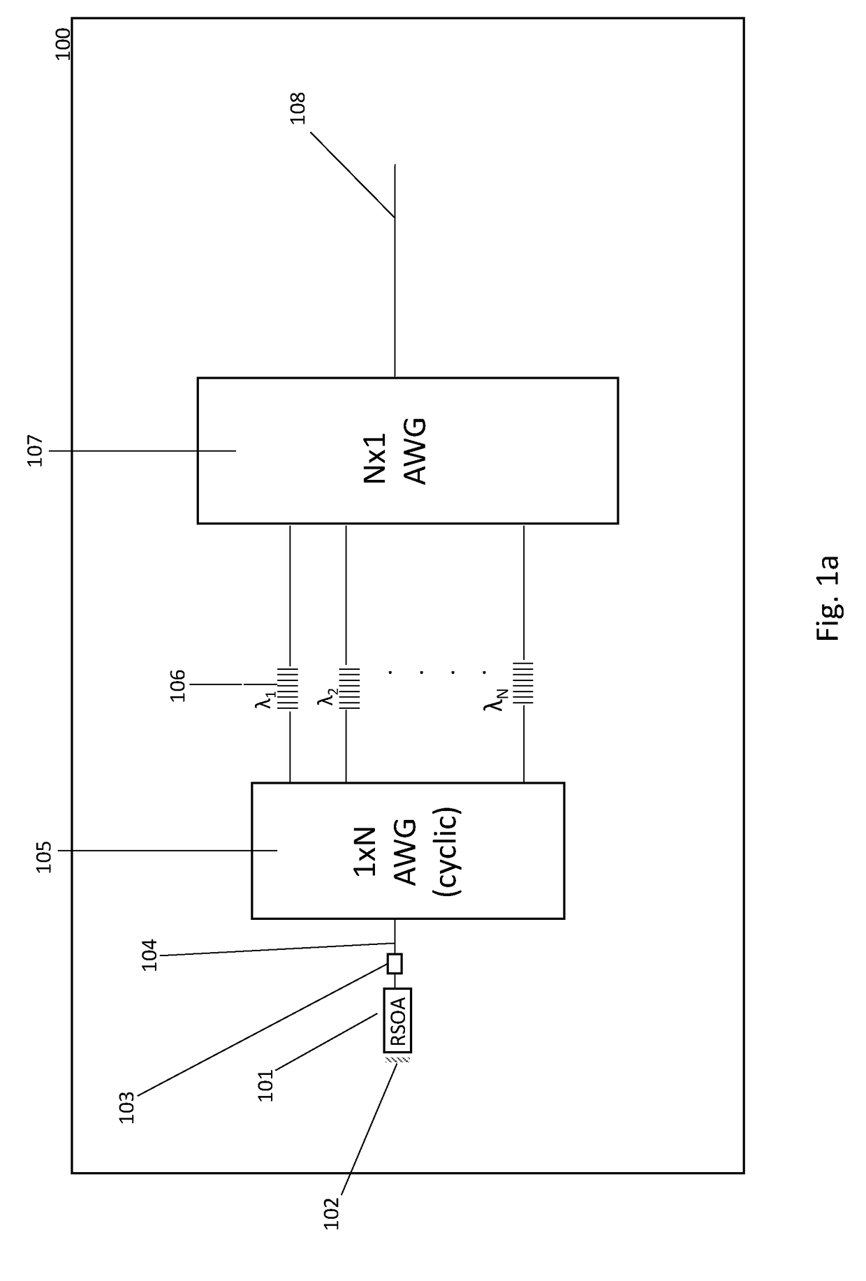
[0041]A first embodiment of a discrete wavelength tunable laser 100 is described with reference to FIGS. 1a and 1b. The discrete wavelength tunable laser 100 includes a semiconductor optical amplifier (SOA) reflective semiconductor optical amplifier (RSOA) 101 which generates light over a given gain bandwidth. The back surface of the RSOA 102 includes a high reflectivity mirror at 102 forming back end mirror of the optical cavity of the tunable laser.

[0042]The tunable laser includes an Arrayed Waveguide Grating (AWG) 105 in the form of a 1×N AWG which has a single input optically coupled to the output of the RSOA via a waveguide 104. A phase tuner 103 is located at the waveguide 104 for fine tuning of the wavelength.

[0043]The AWG has N outputs, each of which transmits or passes a respective fixed spectral passband, each of which lies within the gain bandwidth of the RSOA.

[0044]A plurality N of waveguides are each optically coupled to a respective one of the N outputs of the 1×N AWG....


PUM


Abstract

A discrete wavelength tunable laser having an optical cavity which comprises: a reflective semiconductor optical amplifier (SOA); a demultiplexer (Demux) having a single input and a plurality of outputs, the Demux configured to receive the output of the SOA and to produce a plurality of fixed spectral passbands within the gain bandwidth of the SOA; one or more tunable distributed Bragg reflector(s) (DBR(s)) arranged to receive the outputs of the Demux, each tunable DBR configured to select a reflective spectral band within the gain bandwidth of the SOA upon application of a bias current; wherein the SOA forms the back end mirror of the optical cavity; the one or more tunable DBRs form the front end mirror of the optical cavity; and wherein the lasing channel of the discrete wavelength tunable laser is chosen by the overlap of the selected reflective spectral band of one of the one or more tunable DBRs with a fixed spectral passband of the Demux.

Description

FIELD OF THE INVENTION[0001]The present invention relates to a discrete wavelength tunable laser, particularly to a discrete wavelength tunable laser having an optical cavity which includes a combination of a passive optical grating and one or more digital supermode-distributed Bragg reflector(s).BACKGROUND OF THE INVENTION[0002]Continuously tunable lasers are well-established and are commonplace in telecommunications applications. Although telecommunications lasers operate to fixed grids (eg ITU grids), tunable lasers need to be set up for a variety of applications and some extent of wavelength tunability is desirable to allow for correction of wavelength drift as the laser ages. Unfortunately, the requirement for full range continuous tunability results in expensive and power-hungry electronic circuitry, most particularly due to the requirement for digital-analog conversion (DAC) chips.[0003]Distributed Feedback (DFB) lasers in which the gratings are built into the gain medium are...

Claims


Application Information

Patent Timeline
Patent Type & Authority Applications(United States)
IPC IPC(8): H01S5/125H01S5/50H01S5/068H01S5/026H01S5/12
CPCH01S5/125H01S5/50H01S5/068H01S5/0268H01S5/124H01S5/142H01S5/141H01S5/4012H01S5/4062G02B6/12019G02B6/42H01S5/1092H04J14/02
Inventor ZILKIE, AARON
Owner ROCKLEY PHOTONICS LTD
Why Eureka
Try Eureka