Verification pipette and vision apparatus

a technology of vision apparatus and pipette, which is applied in the field of hand-held devices, can solve the problems of no way to validate whether, no way to track the location of the pipette, and no way to use the handheld pipette devi

Active Publication Date: 2020-10-20
KOBRA BIOSOLUTIONS LLC
View PDF33 Cites 3 Cited by
  • Summary
  • Abstract
  • Description
  • Claims
  • Application Information

AI Technical Summary

Benefits of technology

[0012]In some implementations, the vision system associated with the single and or multi-channel handheld pipette apparatus includes a lighting system and associated logic that helps the vision system recognize and determine when the handheld pipette apparatus, or the pipette tip of the handheld pipette apparatus, is in a proper source container or other proper target location and whether the container is the correct container. The vision system also validates the actual position of the handheld pipette apparatus when liquid is aspirated and dispensed. The system may also be configured to digitally output an image (or series of images or video file(s)), or other associated data, of the pipette tip when it is in the liquid transfer position. The system is also configured to recognize or otherwise determine which container (e.g., which well, test tube etc.) the liquid was transferred from / to.
[0015]The handheld pipette apparatus may also include various rings (e.g., UV rings or various other color differential rings) that may be used in conjunction with the vision system. For example, the rings may be used to differentiate the handheld pipette apparatus from a background of a laboratory or other facility in which the handheld pipette apparatus is being used. The various rings act to increase the accuracy of the readings of the vision system.
[0033]In some embodiments, the handheld pipette apparatus of the present disclosure may be configured to monitor itself and diagnose whether a liquid handling task is being correctly performed, whether there is enough liquid in a tip of the handheld pipette device, whether there is air in the sample and / or whether air is present in the sample, whether the well or test tube is empty and so on. The handheld pipette apparatus and / or the vision system may also determine whether a clot or clog is present in the tip of the handheld pipette apparatus such that improper liquid handling is prevented. This may be accomplished by taking an image of the tip and determining whether a blockage exists, by measuring actual flow rate versus expected flow rate of liquid to and from the pipette tip and so on. The handheld pipette apparatus may also monitor itself and recognize and / or diagnose a malfunction and create an error condition during a liquid handling event to prevent further use until the malfunction is fixed or required service is performed on the equipment.
[0039]In addition, the system may run a recipe / method, from a secure network drive from a remote or common location with the workbench. The system can load, or pull up, pre-validated methods that are stored on a secured network drive. This networked loaded recipe standardizes how samples are processed across different operators, different labs and different sites. With the use of the handheld pipette apparatus, there is no operator technique involved for liquid handling variability issues and no incorrect positional transfers with the vision system validation. This gives companies and government services, like the ATF and FBI crime labs, the ability to standardize processes and document every liquid transfer with quality and defensible data.
[0042]Accordingly, a primary object of the present invention is to provide fluid sample processing environment which can verify fluid sample processing has been conducted according to parameters of a fluid sample processing protocol.

Problems solved by technology

However, there is no way to validate whether the correct liquid, in the correct locations (and amounts) were present when liquid, was aspirated from one source and when the liquid was dispensed at a destination.
Manual electronic handheld pipette devices do not fare much better.
However, nothing tracks the location of the pipette when aspirating and / or dispensing liquid.
Also, the parameters that equate the movement of the motor to the volume of the liquid drawn fall out of calibration and can become inaccurate due to the wearing of internal seals, so that volume information loses reliability.

Method used


Image

  • Verification pipette and vision apparatus
  • Verification pipette and vision apparatus
  • Verification pipette and vision apparatus

Examples


Embodiment Construction

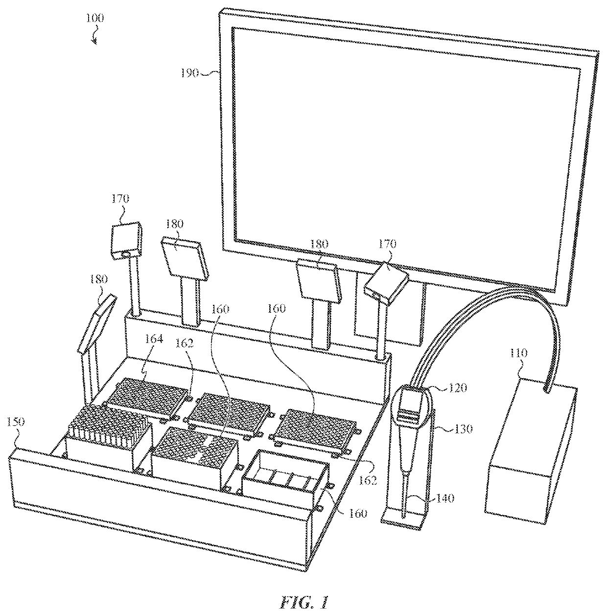
[0055]Referring to the drawings, wherein like reference numerals represent like parts throughout the various drawing figures, reference numeral 100 (FIG. 1) is directed to a system for processing a fluid sample in a verified manner. FIG. 1 illustrates an exemplary embodiment system 100 for collecting and monitoring the aspiration and dispensing of liquid using a handheld pipette apparatus 120, such as described above.

[0056]As shown in FIG. 1, the system 100 includes a pipetting controller 110 and the handheld pipette apparatus 120. The handheld pipette apparatus 120 may be connected to the pipetting controller 110 wirelessly, or using various communication, air, power and / or pressure and vacuum tubes. The pipetting controller 110 may be used to monitor and control the dispensing and aspiration of liquid such as described above, or just for passive documentation of pipette 120 tip 140 position (and optionally orientation) at meaningful times, such as when aspirating or dispensing.

[00...


PUM

PropertyMeasurementUnit
angleaaaaaaaaaa
sizeaaaaaaaaaa
volumeaaaaaaaaaa

Abstract

Manually operated pipettors, widely used in clinical, forensics, pharmaceutical research, hospital and biotech laboratories to transfer small volumes of liquid, may be subject to positional errors, operator use errors and hidden performance degradation. Manual pipette performance cannot be accepted without monitoring and reporting. This invention concerns a computer controlled vision tracking and lighting system working in conjunction with a sensor controlled fluid dispensing device and controller to confirm pipette tip positional locations during aspiration and dispensing operations with automatic monitoring of liquids entering and leaving a pipette apparatus to digitally track a manual pipetting operation with a digital output file of validated liquid transfer results. The invention may also monitor possible error conditions and prevent improper liquid transfers during the manual process.

Description

CROSS-REFERENCE TO RELATED APPLICATIONS[0001]This application claims benefit under Title 35, United States Code § 119(e) of U.S. Provisional Application No. 62 / 354,327 filed on Jun. 24, 2016.FIELD OF THE INVENTION[0002]The present invention generally relates to handheld devices for transferring and measuring liquids. More specifically, the present disclosure is directed to a handheld pipette apparatus and vision system for accurately drawing measured amounts of liquid from and accurately dispensing liquid into a microplate, well, tray or test tube as well as tracking and reporting positional location of the handheld pipette apparatus, such as for verification and control purposes.BACKGROUND OF THE INVENTION[0003]Current handheld electronic pipettes are manually operated and do not track or otherwise output information regarding where liquid was removed from (aspirated) or, where the liquid was dispensed.[0004]For instance, in typical manual handheld pipette devices, an operator manu...

Claims


Application Information

Patent Timeline
Patent Type & Authority Patents(United States)
IPC IPC(8): B01L9/00C12M1/34C12Q1/6806G06K9/00G06T7/00G06K9/36B01L3/02G01N1/10G01N35/10G01N1/00G01N35/00G01N35/04G06V20/52G06V20/66
CPCG01N35/1011G06K9/00771B01L9/56G06K9/36B01L3/021G01N1/10C12Q1/6806G01N35/1016C12M1/34G06T7/0012G01N35/00G06K9/00G01N2035/0494B01L2200/143G01N1/00G06T2207/30004G01N35/1065G06V20/52G06V20/66G06F18/00
Inventor HURWITZ, JEFFREY P.CORKAN, LLOYD ANDREW
Owner KOBRA BIOSOLUTIONS LLC
Why Eureka
Try Eureka