Method and apparatus for applying a topical solution

a topical solution and application method technology, applied in the field of topical solution application methods and apparatuses, can solve the problems of reducing limiting the overall size and basic packaging of the applicator, and reducing the likelihood of structural instability of the ampoules. , to achieve the effect of reducing the likelihood, increasing the available volume for storage, and maintaining a compact structur

Active Publication Date: 2020-10-27
DUSA PHARMA INC
View PDF5 Cites 5 Cited by
  • Summary
  • Abstract
  • Description
  • Claims
  • Application Information

AI Technical Summary

Benefits of technology

[0007]In addition, when crushing an applicator such as the one disclosed in U.S. Pat. No. 5,954,703, the user must apply pressure directly to the surface of the container using his hands. This presents the possibility of an uneven application of force to the ampoules, resulting in the possibility that not all of the ampoules are broken. This, in turn, may reduce the likelihood that the components of the solution are properly mixed before application to the intended treatment area.
[0008]Therefore, it is an object of some embodiments of the present invention to increase the available volume for storage of the ALA solution components while maintaining a compact structure. It is also an object of some embodiments of the present invention to provide a sufficiently reliable and controlled breaking mechanism for the proper mixing of the ALA solution.

Problems solved by technology

Such sizing up of the glass ampoules, however, may be relatively difficult to achieve because the walls of the ampoules must remain sufficiently thin to allow for easy breakage.
Thus, by increasing the size of the glass ampoules while retaining the thin walls increases the likelihood of structural instability of the ampoules.
In addition, regulations governing pharmaceutical packaging may further constrain the overall size and basic packaging of the applicator.
This presents the possibility of an uneven application of force to the ampoules, resulting in the possibility that not all of the ampoules are broken.
This, in turn, may reduce the likelihood that the components of the solution are properly mixed before application to the intended treatment area.

Method used


Image

  • Method and apparatus for applying a topical solution
  • Method and apparatus for applying a topical solution
  • Method and apparatus for applying a topical solution

Examples


Embodiment Construction

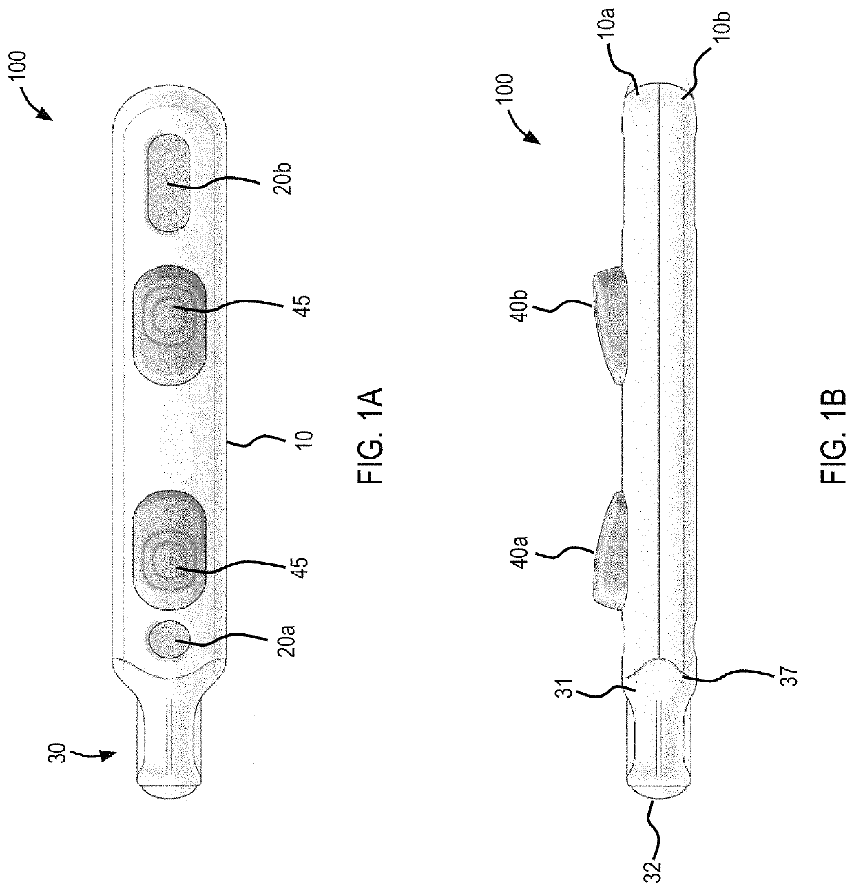
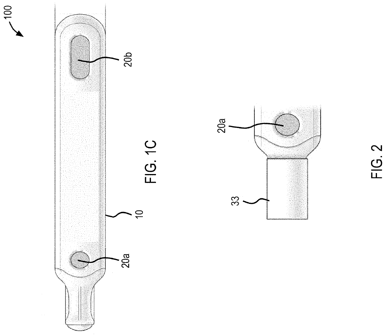
[0017]FIGS. 1A-1C illustrate one embodiment of an applicator according to the present invention. As shown in FIGS. 1A-1C, the applicator 100 is formed as a tertiary structure having a case 10, which includes two separate parts 10a and 10b fitted together along a midline, and an applicator head 30 attached to one end of the case 10. The case 10 may be generally oblong in shape, but may be any other appropriate shape, while the applicator head 30 tapers from the case 10 and narrows to form a ball-point tip or other type of applicator tip. The case 10 and the applicator head 30 may be made of any suitable material. Preferably, the case 10 and the applicator head 30 are made of a rigid plastic material, such as polyvinyl chloride (PVC).

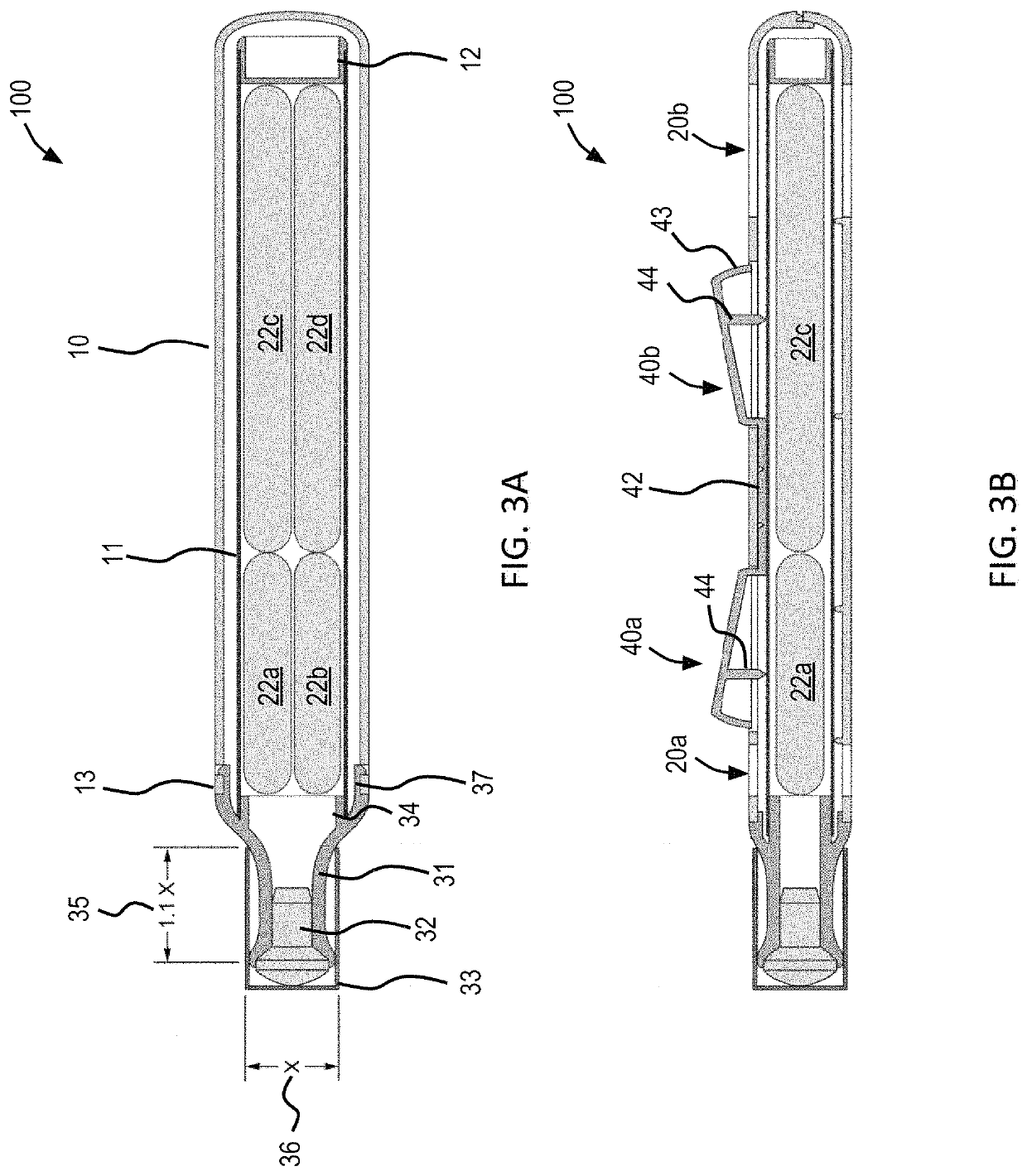
[0018]The applicator head 30 further includes a frame 31 and an applicator pad 32 attached to one end of the frame 31. As shown in FIG. 3A, at an opposite end of the frame 31, the frame 31 includes a recessed portion 37, which is formed to receive a protr...


PUM


Abstract

An applicator for dispensing a solution having two or more components includes a hollow body having a head provided at one end of the hollow body for dispersion of the solution and a breaking mechanism attached to the hollow body. The breaking mechanism includes at least one projection extendable into an interior of the hollow body. The applicator further includes a plurality of ampoules placed in the interior of the hollow body. The plurality of ampoules contains the two or more components. Upon activation of the breaking mechanism, the at least one projection applies a force to the plurality of ampoules such that the plurality of ampoules break and release the two or more components to form the solution.

Description

CROSS-REFERENCE TO RELATED PATENT APPLICATION[0001]The present application claims the benefit of priority to U.S. Provisional Application No. 62 / 264,510, filed Dec. 8, 2015, the contents of which is hereby incorporated by reference in its entirety.FIELD[0002]The invention relates generally to an apparatus and method for supplying, mixing, and applying a solution having two or more components for topical use.BACKGROUND[0003]Photodynamic therapy (PDT), photodynamic diagnosis (PD), or photochemotherapy is generally used to treat and / or diagnose several types of ailments in or near the skin or other tissues, such as those in a body cavity. During one form of PDT or PD, a patient is first administered a photoactivatable agent or a precursor of a photoactivatable agent that accumulates in the tissue to be treated or diagnosed. The area in which the photoactivatable agent is administered is then exposed to visible light, which causes chemical and / or biological changes in the agent. These c...

Claims


Application Information

Patent Timeline
Patent Type & Authority Patents(United States)
IPC IPC(8): A61M35/00A61J1/20A61J1/06A61K41/00A61N5/06
CPCA61M35/003A61J1/2089A61N5/062A61K41/0061A61J1/065
Inventor BOYAJIAN, THOMASCAROTA, MARK
Owner DUSA PHARMA INC
Why Eureka
Try Eureka