System for determining occurrence of an automobile accident and characterizing the accident

a technology for automobile accidents and occurrence, applied in the direction of instruments, pedestrian/occupant safety arrangements, biological models, etc., can solve the problems of system generating a false positive, and generating a false negativ

Active Publication Date: 2020-10-27
TANGERINE INNOVATION HLDG INC
View PDF6 Cites 10 Cited by
  • Summary
  • Abstract
  • Description
  • Claims
  • Application Information

AI Technical Summary

Benefits of technology

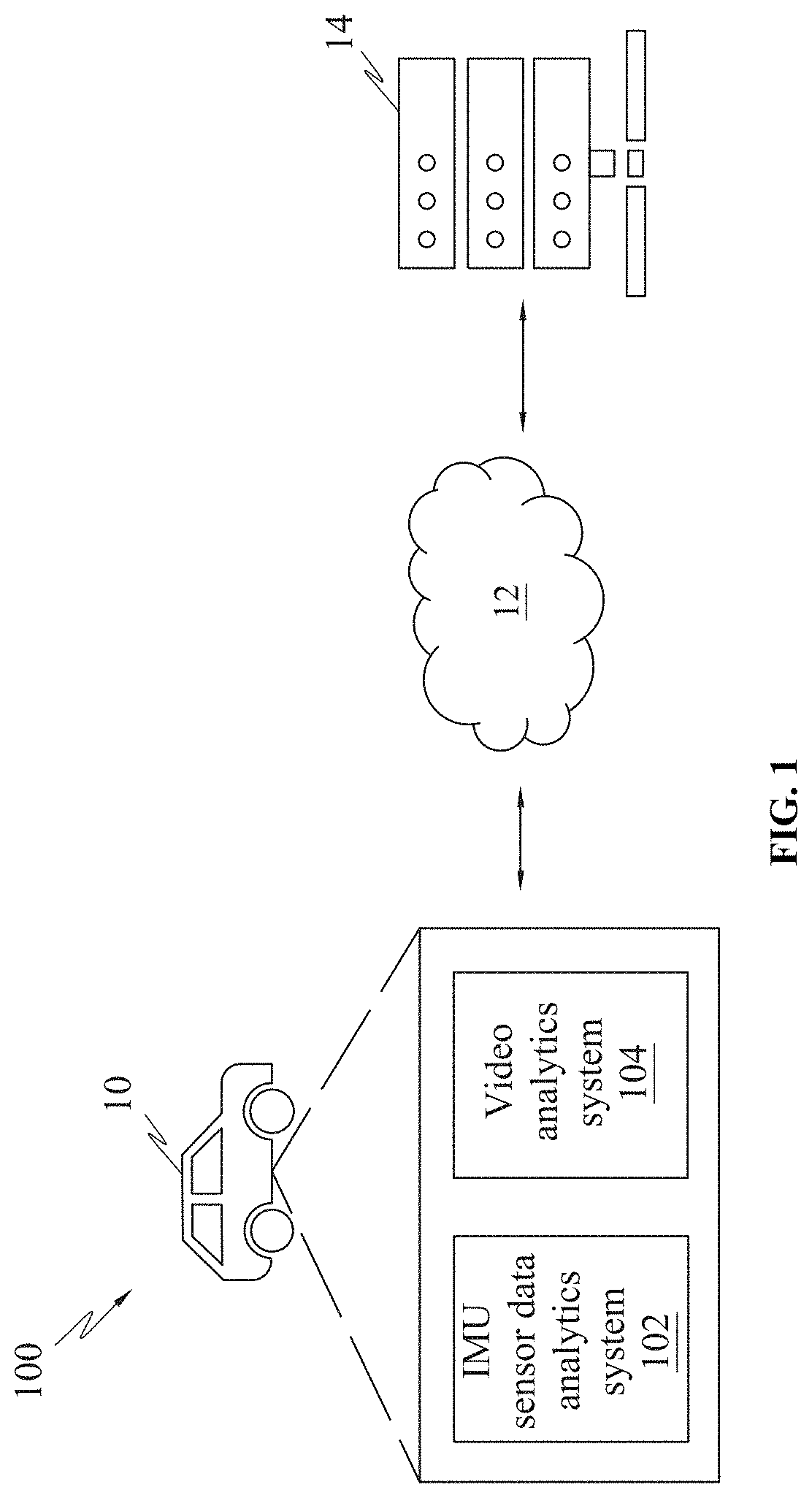
[0009]A system for determining occurrence of automobile accidents and characterizing the accidents comprises a camera system and one or more video processors. The camera system is disposed in the automobile to capture video. The video processors are configured to feed at least a portion of video captur

Problems solved by technology

In such cases, the system may generate a false positive.
As an example, the system may generate a false positive when the driver appl

Method used


Image

  • System for determining occurrence of an automobile accident and characterizing the accident
  • System for determining occurrence of an automobile accident and characterizing the accident
  • System for determining occurrence of an automobile accident and characterizing the accident

Examples


second embodiment

[0095]FIG. 11 is a flowchart 1100, illustrating training of the deep machine learning model 804, in accordance with another (second embodiment) embodiment.

[0096]In an embodiment, at step 1102, the neural network may receive a plurality of training videos. The training videos may be of varying lengths.

[0097]In an embodiment, at step 1104, each of the plurality of the videos may be divided into plurality of segments. The number of segments may vary. Referring to FIG. 12, the plurality of segments may include a first segment 1202, a second segment 1204, a third segment 1206 and so on.

[0098]In an embodiment, at step 1106, each segment 1202, 1204, 1206 may further be divided into a plurality of frames.

[0099]In an embodiment, at step 1108, the frames of the first segment 1202 may be fed to the neural network in a form of sequence to study the optical flow across the consecutive frames of the first segment 1202. As an example, video of 4 seconds may be divided into 4 segments, wherein each...

third embodiment

[0119]FIGS. 14A-B depict a flowchart 1400, illustrating yet another method of training deep learning model 804 of the video analytics system 104, in accordance with another embodiment (third embodiment).

[0120]In an embodiment, referring to FIG. 14A, at step 1402, a plurality of training videos may be fed. The video may be divided into plurality of video frames.

[0121]In an embodiment, at step 1404, features corresponding to objects present in the video frames may be extracted. The features may correspond to objects present in the video frames.

[0122]In an embodiment, at step 1406, the object features may be fed to a neural network. The neural network may be LSTM. The LSTM may be trained to identify a third party automobile 10 using an attention mechanism, wherein the third party automobile 10 may be a foreign automobile 10 which may be involved in the accident. The attention mechanism may decide the feature on which the neural network should pay attention on. As an example, the attent...


PUM


Abstract

A deep learning based computer vision system to detect and analyses automobile crash videos comprises a crash detection module and a crash analysis module. The crash detection module uses dashcam video and or telemetry to detect the same. The usage of computer vision algorithm alongside the IMU sensor data make the system robust. The system uses a deep learning model which looks for an anomalous pattern in the video and/or the IMU signal to detect a crash. The system comprises different machine learning and deep learning based computer vision algorithm to analyze the crash detected videos. The system automates the labor-intensive task of reviewing crash videos and generates a crash report comprising accident type, road surface, weather condition and accident scenario among other things. The accident detection and analysis modules can reside on the vehicle as well as on the cloud based on the compute capabilities of the edge device.

Description

BACKGROUND[0001]Unless otherwise indicated herein, the materials described in this section are not prior art to the claims in this application and are not admitted to being prior art by inclusion in this section.FIELD OF THE INVENTION[0002]The subject matter in general relates to system for detecting automobile accidents. More particularly, but not exclusively, the subject matter relates to determining and characterizing automobile accidents using computer vision and deep learning techniques.DISCUSSION OF THE RELATED ART[0003]Detailed information relating to an automobile accident is required to accurately assess the damage and loss associated with an accident. Information pertaining to the accident further helps in analysing the cause of the accident, percentage of negligence of the driver and so on. The detailed information may be obtained from sensor devices on-board vehicle or from video recording, recorded by the dash camera.[0004]Telemetry has been widely used worldwide for an...

Claims


Application Information

Patent Timeline
IPC IPC(8): B60Q1/00G07C5/08B60R21/0136G06N20/00
CPCG07C5/0866B60R21/0136G06N20/00B60R21/013B60R21/0132G06N3/084G06N3/088G06N20/10G06N20/20G06N5/01G06N3/045G06N3/044
Inventor RISHI, SUNIJARISHI, SUMITKOCHHAR, AYUSHOLIYIL UNNIKRISHNAN, NIRMAL JITHBADAGA, PRASHANTKUMAR, VINOD
Owner TANGERINE INNOVATION HLDG INC
Why Eureka
Try Eureka