Torsional vibration damper and manufacturing method thereof

a technology manufacturing method, which is applied in the manufacture of springs/dampers, rotating vibration suppression, shock absorbers, etc., can solve the problems of increased man-hour and manufacturing cost of damper, inability to achieve intended damping performance, and inability to enhance the vibration damping performance of damper, so as to enhance the vibration damping performance of torsional vibration damper, the effect of reducing processing cos

Active Publication Date: 2020-10-27
TOYOTA JIDOSHA KK
View PDF13 Cites 4 Cited by
  • Summary
  • Abstract
  • Description
  • Claims
  • Application Information

AI Technical Summary

Benefits of technology

[0006]The present disclosure has been conceived noting the foregoing technical problems, and it is therefore an object of the present disclosure is to enhance a vibration damping performance of a torsional vibration damper without increasing a manufacturing cost significantly.
[0011]Thus, according to the embodiment of the present disclosure, hardness of the contact surface of any one of the inertia body and the rolling mass is harder than the contact surface of the other one of the inertia body and the rolling mass, and smoothness of the contact surface of said any one of the inertia body and the rolling mass is smoother than the contact surface of the other one of the inertia body and the rolling mass. That is, a coefficient of friction of the contact surface that is harder than the other contact surface is smaller than a coefficient of friction of the other contact surface. According to the embodiment of the present disclosure, therefore, the rolling mass centrifugally pushed onto a raceway surface of the inertia body is allowed to oscillate smoothly along the raceway surface in a desired order to enhance vibration damping performance of the torsional vibration damper.
[0012]As described, any one of the inertia body and the rolling mass is made of harder material than the other one. According to the embodiment of the present disclosure, therefore, abrasion of the contact surface of the inertia body or the rolling mass made of softer material due to oscillation of the rolling mass is expedited, and eventually the surface roughness of the softer contact surface will be substantially equalized to the harder contact surface. That is, the vibration damping performance of the torsional vibration damper can be enhanced by polishing only one of the inertia body and the rolling mass, as the case of polishing both of the inertia body and the rolling mass. In addition, since only the contact surface of any one of the inertia body and the rolling mass is polished, a processing cost can be reduced compare to the conventional art in which both of the inertia body and the rolling mass are polished. As a result, a manufacturing cost of the torsional vibration damper can be reduced. Further, a man-hour for manufacturing the torsional vibration damper may also be reduced.
[0013]Further, given that the rolling mass is made of material harder than material of the rotary member, a surface of the rotary member contacted to the rolling mass may also be smoothened by a centrifugal displacement of the rolling mass. As a result, roughness of the surface of the rotary member contacted to the rolling mass will also be equalized to that of the rolling mass. Acceding to the embodiment of the present disclosure, therefore, members involving vibration damping action of the torsional vibration damper are allowed to move smoothly in the torsional vibration damper.
[0014]According to the manufacturing method of the present disclosure, the contact surface of any one of the inertia body and the rolling mass is formed using the material harder than the material of the contact surface of other one of the inertia body and the rolling mass, and the contact surface of said any one of the inertia body and the rolling mass is polished smoother than the contact surface of the other one of the inertia body and the rolling mass. Thereafter, the torsional vibration damper is assembled using the rolling mass and the inertia body thus prepared. According to the manufacturing method of the present disclosure, therefore, the torsional vibration damper that can achieve the above-explained advantages can be assembled easily by the simple procedure.

Problems solved by technology

However, a man-hour and a manufacturing cost of the damper would be increased as a result of smoothing the raceway surface and the contact surface of the rolling mass.
Nonetheless, an intended damping performance may not be achieved, or the vibration damping performance of the damper may not be enhanced without reducing the friction coefficient between the raceway surface and the contact surface of the rolling mass.

Method used


Image

  • Torsional vibration damper and manufacturing method thereof
  • Torsional vibration damper and manufacturing method thereof
  • Torsional vibration damper and manufacturing method thereof

Examples


Embodiment Construction

)

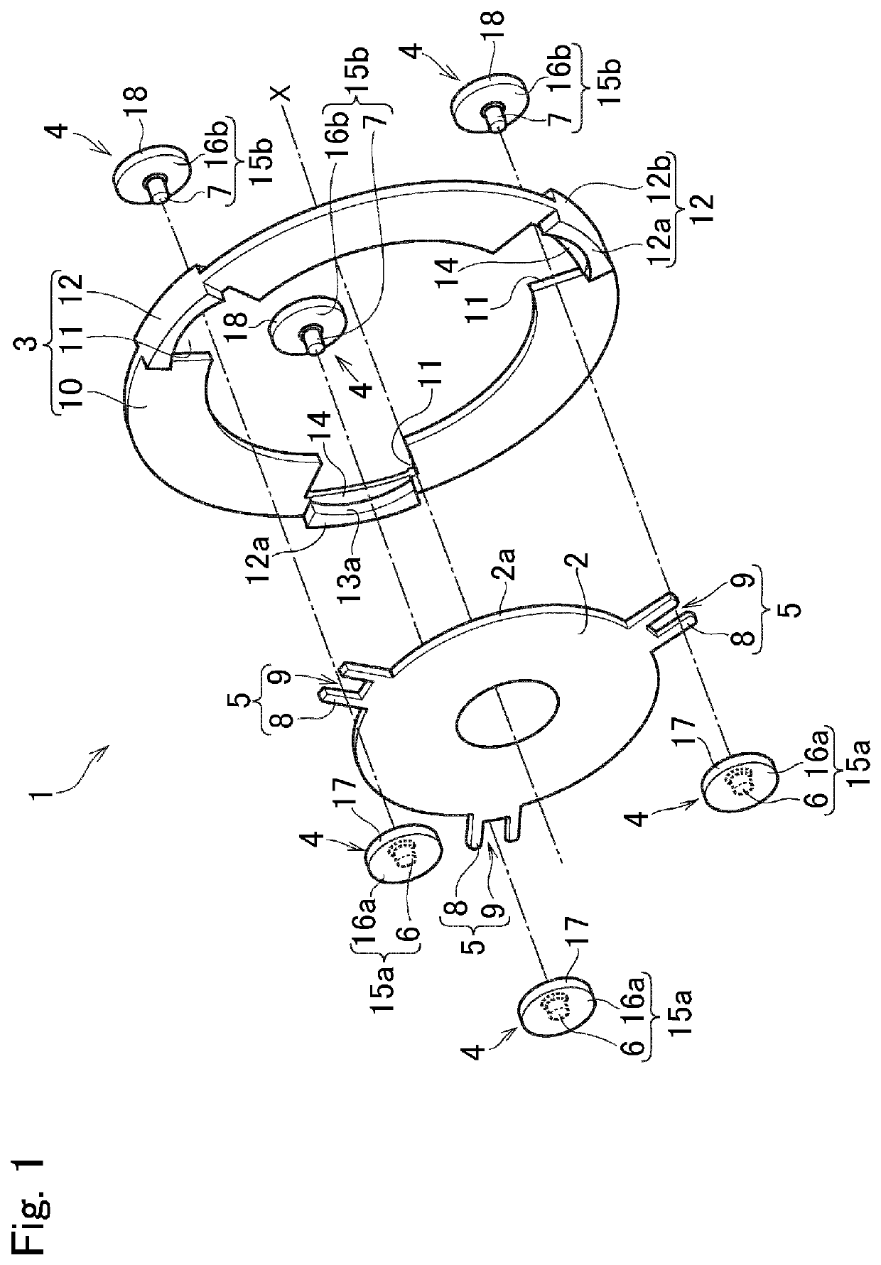
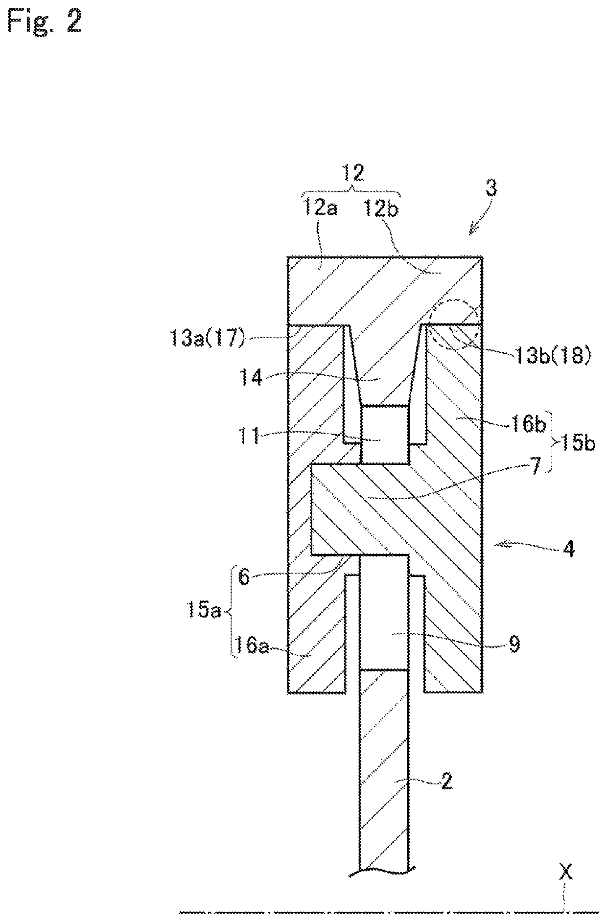
[0021]A preferred embodiment of the present disclosure will now be explained with reference to the accompanying drawings. For example, a torsional vibration damper according to the embodiment of the present disclosure is applied a vehicle to reduce torsional vibrations resulting from pulsation of a torque delivered from an engine to a transmission. FIG. 1 is an exploded perspective view showing constitutional elements of a torsional vibration damper 1 according to the embodiment of the present disclosure, and FIG. 2 is a partial cross-sectional view showing a cross-section of the torsional vibration damper 1 in a situation where a rolling mass is centrifugally pushed onto a raceway surface.

[0022]The torsional vibration damper 1 comprises a rotary member 2 that is rotated by a torque applied thereto, an inertia body 3 that is rotated relatively to the rotary member 2 by a torque pulse or a torque change, and a plurality of rolling mass 4 individually serving as a connection member c...


PUM


Abstract

A torsional vibration damper in which a vibration damping performance is enhanced without increasing a manufacturing cost. A torsional vibration damper damps torsional vibrations by a relative rotation between a rotary member and an inertia body. Hardness of the contact surface of any one of the inertia body and a rolling mass is harder than the contact surface of the other one. Smoothness of the contact surface of any one of the inertia body and the rolling mass is smoother than the contact surface of the other one.

Description

[0001]The present invention claims the benefit of Japanese Patent Applications No. 2018-48999 filed on Mar. 16, 2018, and No. 2018-134869 filed on Jul. 18, 2018 with the Japanese Patent Office, the disclosures of which are incorporated herein by reference in their entirety.BACKGROUNDField of the Invention[0002]Embodiments of the present disclosure relate to the art of a torsional vibration damper that reduces a torsional vibration resulting from a pulsation of an input torque, and a manufacturing method thereof.Discussion of the Related Art[0003]JP-A-2017-145857 describes one example of a torsional vibration damper for reducing torsional vibrations resulting from torque pulse by an inertia torque of an inertial mass. The damper taught by JP-A-2017-145857 comprises a rotary member rotated by a torque, an inertial member rotated relatively to the rotary member by a torque pulse, and a connection member as a rolling mass connecting the rotary member and the inertial member in a torque ...

Claims


Application Information

Patent Timeline
Patent Type & Authority Patents(United States)
IPC IPC(8): F16F15/14F16F15/315
CPCF16F15/3156F16F15/1457F16F2226/02F16F2224/0208F16F2226/04F16F2226/026F16F2232/02F16F15/145
Inventor ISHIBASHI, MASAYUKI
Owner TOYOTA JIDOSHA KK
Why Eureka
Try Eureka