
Partitioned variable inclination continuous transverse stub array

a technology of variable inclination and array, applied in the direction of antenna details, antenna adaptation in movable bodies, antennas, etc., to achieve the effect of less weight and cost and more antenna gain

Active Publication Date: 2020-10-27
THINKOM SOLUTIONS
View PDF5 Cites 3 Cited by
  • Summary
  • Abstract
  • Description
  • Claims
  • Application Information

AI Technical Summary

Benefits of technology

The patent describes a new type of antenna that can work with multiple frequency bands and polarize signals. It is flexible and efficient, and can be packaged in a smaller way than other antennas. This makes it useful for applications where space is limited. It also reduces the amount of hardware needed, resulting in a significant weight savings.

Problems solved by technology

Conventional antenna arrays have utilized the concept of feeding a partitioned VICTS array with separate feeds to support two polarizations at the same frequency band, not two separate frequency bands, the latter of which presents additional key design challenges

Method used


Image

  • Partitioned variable inclination continuous transverse stub array
  • Partitioned variable inclination continuous transverse stub array
  • Partitioned variable inclination continuous transverse stub array

Examples


Embodiment Construction

[0054]Embodiments of the present invention will now be described with reference to the drawings, wherein like reference numerals are used to refer to like elements throughout. It will be understood that the figures are not necessarily to scale.

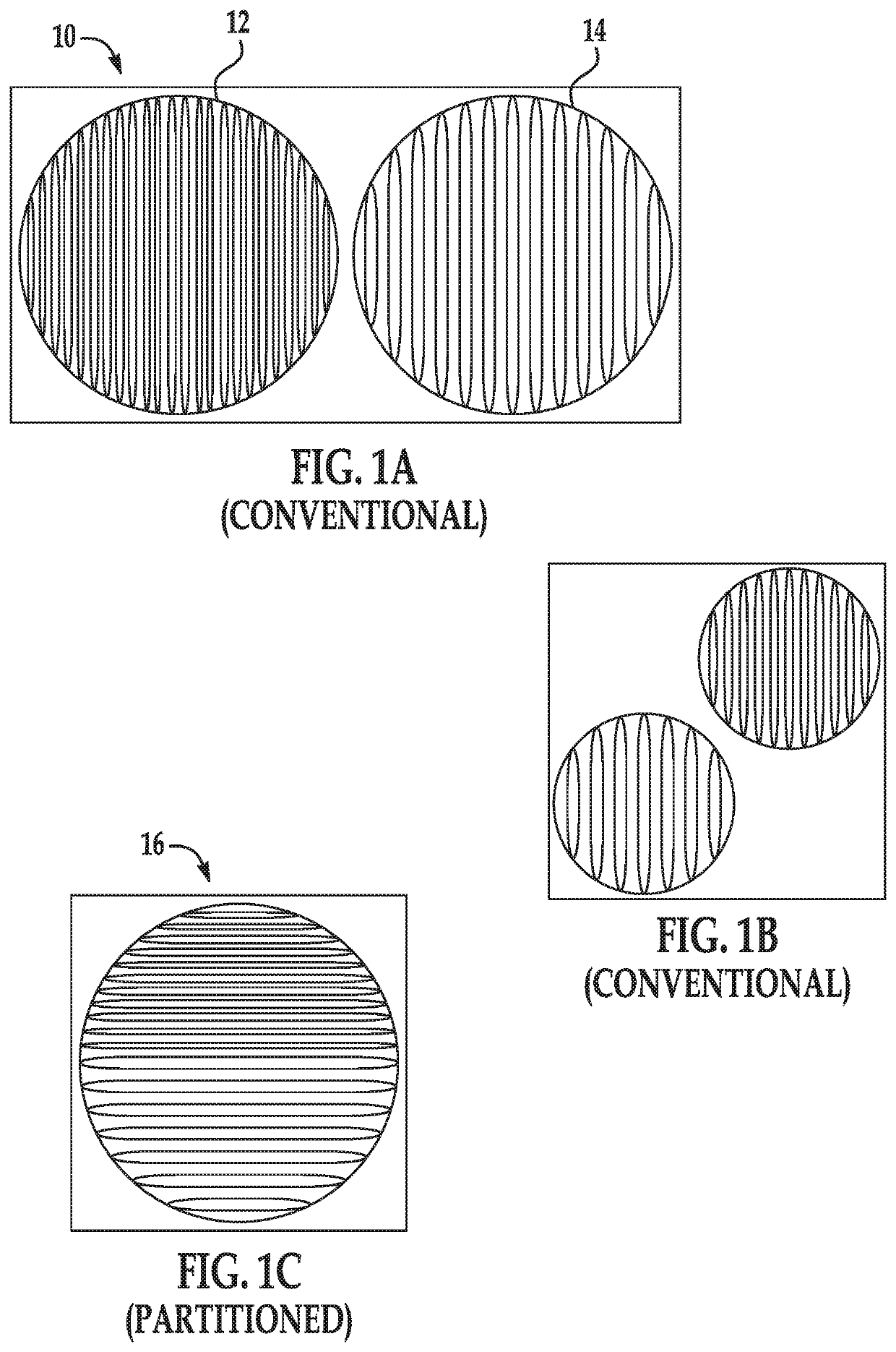
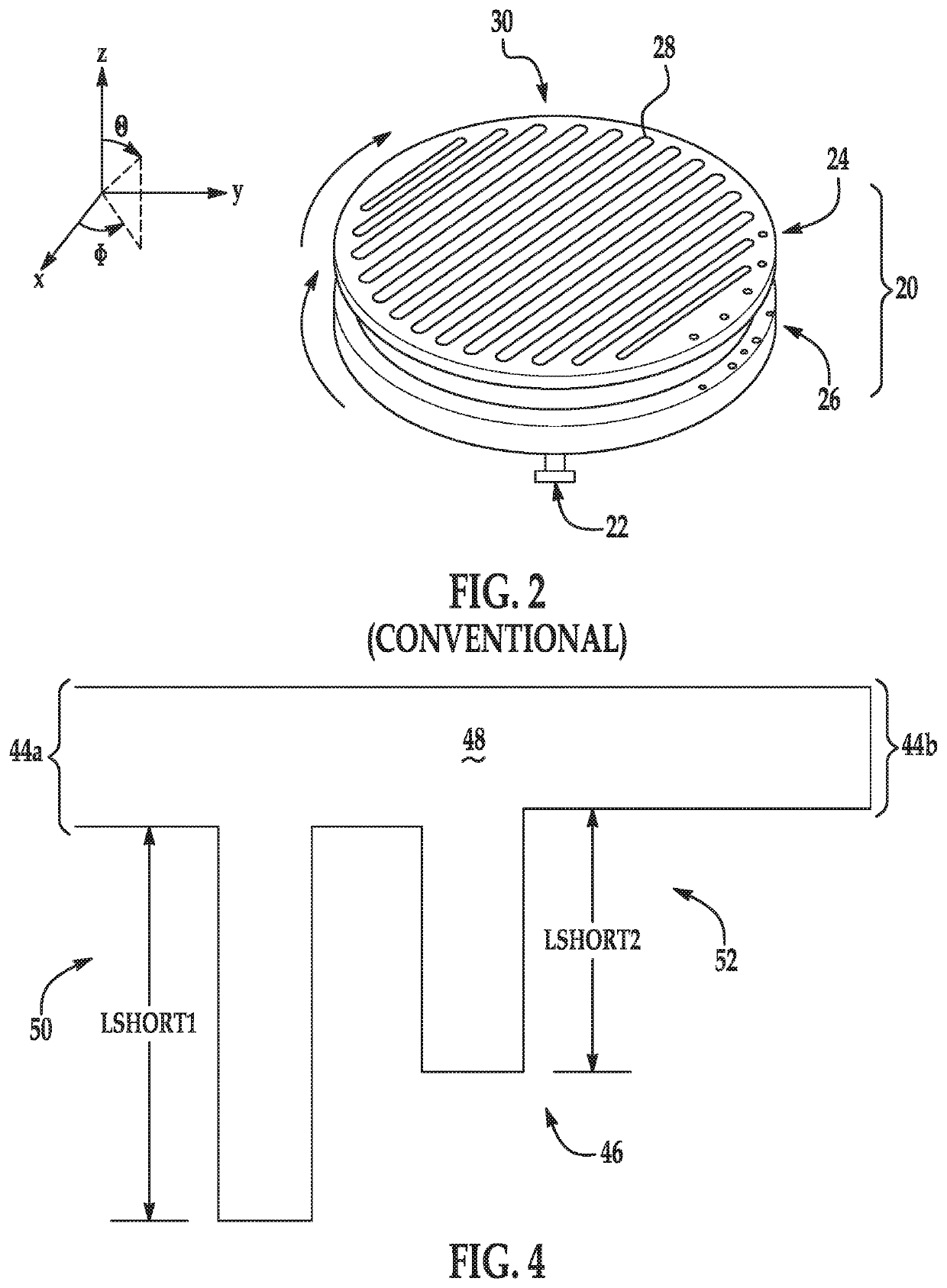
[0055]A VICTS antenna in its simplest form is comprised of two concentric conducting plates, one containing an aperture and one containing a feed. With reference to FIG. 2, illustrated is an exploded view of a typical VICTS antenna 20 embedded in a spherical coordinate system. The VICTS antenna 20 includes a port 22 for receiving / outputting an RF signal, and lower and upper conducting plates 24 and 26 as is conventional. The upper conducting plate 24 includes a plurality of stubs 28 that define an aperture 30 of the VICTS antenna 20. Antenna main beam scanning in θ is achieved via the differential rotation of the aperture with respect to the feed. This type of rotation also scans the antenna main beam over a small range of ϕ (azimuth), while a...


PUM


Abstract

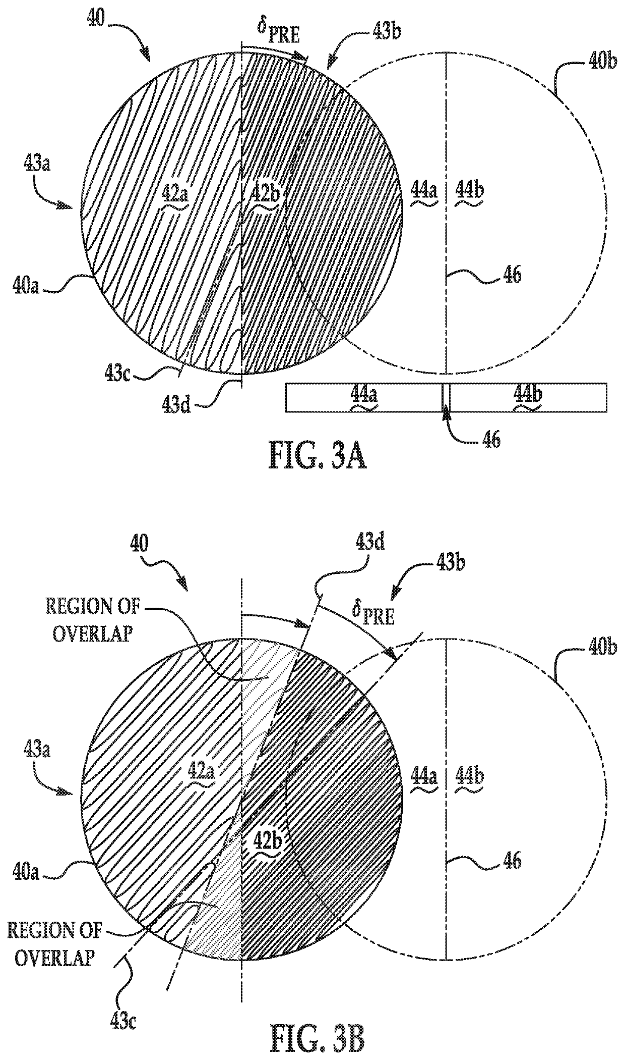
A variable inclination continuous transverse stub antenna includes a first conductive plate and a second conductive plate spaced relative to the first conductive plate. The first conductive plate includes a first surface partitioned into a first region and a second different region, a first group of CTS radiators on the first region, and a second group of CTS radiators on the second region. A spacing and a width in an E-field direction of the first group of radiators is different in respect to a spacing and width in the E-field direction of the second group of radiators. The second conductive plate includes a second surface parallel to the first surface, the second surface partitioned into a first parallel plate transmission line and a second different parallel plate transmission line, the first and second parallel plate transmission lines configured to receive or output a different radio frequency signals from one another.

Description

TECHNICAL FIELD[0001]The present invention relates generally to antennas, and more particularly, to a partitioned variable inclination continuous transverse stub antenna.BACKGROUND ART[0002]Variable inclination continuous transverse stub (VICTS) antenna arrays, due to their inherent low profile and low volume footprint, are a proven antenna solution for systems with demanding installation and packaging requirements. One common installation footprint includes a long (rectangular) narrow volume compatible with aeronautical fuselage crown mount configurations. Another common installation footprint includes a square volume typical of that available on an aircraft wing or terrestrial automobile roof mount configurations.[0003]FIG. 1A shows a top view of an exemplary dual VICTS installation 10, whereby two VICTS arrays 12, 14 are placed side-by-side in a way that lends itself to a long narrow volume installation. In this configuration, one VICTS array 12 may support a data uplink function...

Claims


Application Information

Patent Timeline
Patent Type & Authority Patents(United States)
IPC IPC(8): H01Q21/00H01Q13/06H01Q1/28
CPCH01Q1/283H01Q13/065H01Q13/28H01Q15/244H01Q15/246H01Q3/32H01Q5/55
Inventor MILROY, WILLIAMLEMONS, ALAN
Owner THINKOM SOLUTIONS
Learn More