Active antenna system, mobile terminal, and configuration method of antenna system

a technology of active antenna and mobile terminal, applied in the field of communication, can solve the problems of terminal disconnection, difficult to design a compact antenna that works desirably in a wide frequency range, terminal power consumption greatly reduced, etc., to improve the transmit power and the receiving sensitivity of the terminal, and prolong the battery life.

Active Publication Date: 2021-01-05
ZTE CORP
View PDF17 Cites 0 Cited by
  • Summary
  • Abstract
  • Description
  • Claims
  • Application Information

AI Technical Summary

Benefits of technology

[0005]Embodiments of the present disclosure provide an active antenna system, a mobile terminal, and a configuration method of an antenna system in order to at least solve the problem in the related art that, when an active antenna is in use, power consumption of a terminal is increased due to enlargement of a signal radiation range of the terminal.
[0027]According to the present disclosure, through coupling the active antenna system to the active power amplifier in a detachably manner, the active power amplifier can be electrically coupled to an electronic device as an expandable independent module. In this way, while improving the transmit power and the receiving sensitivity of the terminal, it is also possible to make the power amplifier of the mobile terminal entity have no need to work when the active power amplifier is in use. Thus, the power consumption of the terminal itself is greatly reduced, and the battery life is further endurable. In addition, when used for a long time or in high intensity, the processor is also less likely to be down-converted due to overheating, which avoids terminal disconnection due to terminal overheating having an impact on the terminal performance, thereby ensuring normal operation of the terminal.

Problems solved by technology

In order to meet consumer demand for small wireless devices, the available space of a mobile terminal antenna is getting smaller and smaller, but it is difficult to design a compact antenna that works desirably in a wide frequency range.
However, the smaller the terminal volume, the more difficult it is to dissipate heat when the transmitting power increases to enlarge the signal radiation range.
Long time or high-intensity use would cause overheating of a processor, which may result in problems such as terminal disconnection.
With respect to the above problem, no efficient solution has been proposed yet.

Method used


Image

  • Active antenna system, mobile terminal, and configuration method of antenna system
  • Active antenna system, mobile terminal, and configuration method of antenna system
  • Active antenna system, mobile terminal, and configuration method of antenna system

Examples


embodiment 1

[0041]In this embodiment, an active antenna system is provided. As used hereinafter, the term “unit” can implement a combination of software and / or hardware of predetermined functions. Although the devices described in the following embodiments are preferably implemented through software, hardware or a combination of software and hardware is also possible and contemplated.

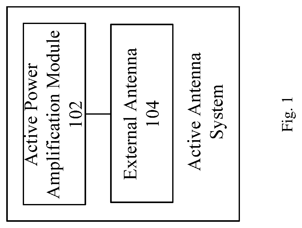
[0042]FIG. 1 is a block diagram showing a structure of an active antenna system according to this embodiment. As shown in FIG. 1, the system comprises an active power amplifier 102 and a passive antenna 104,

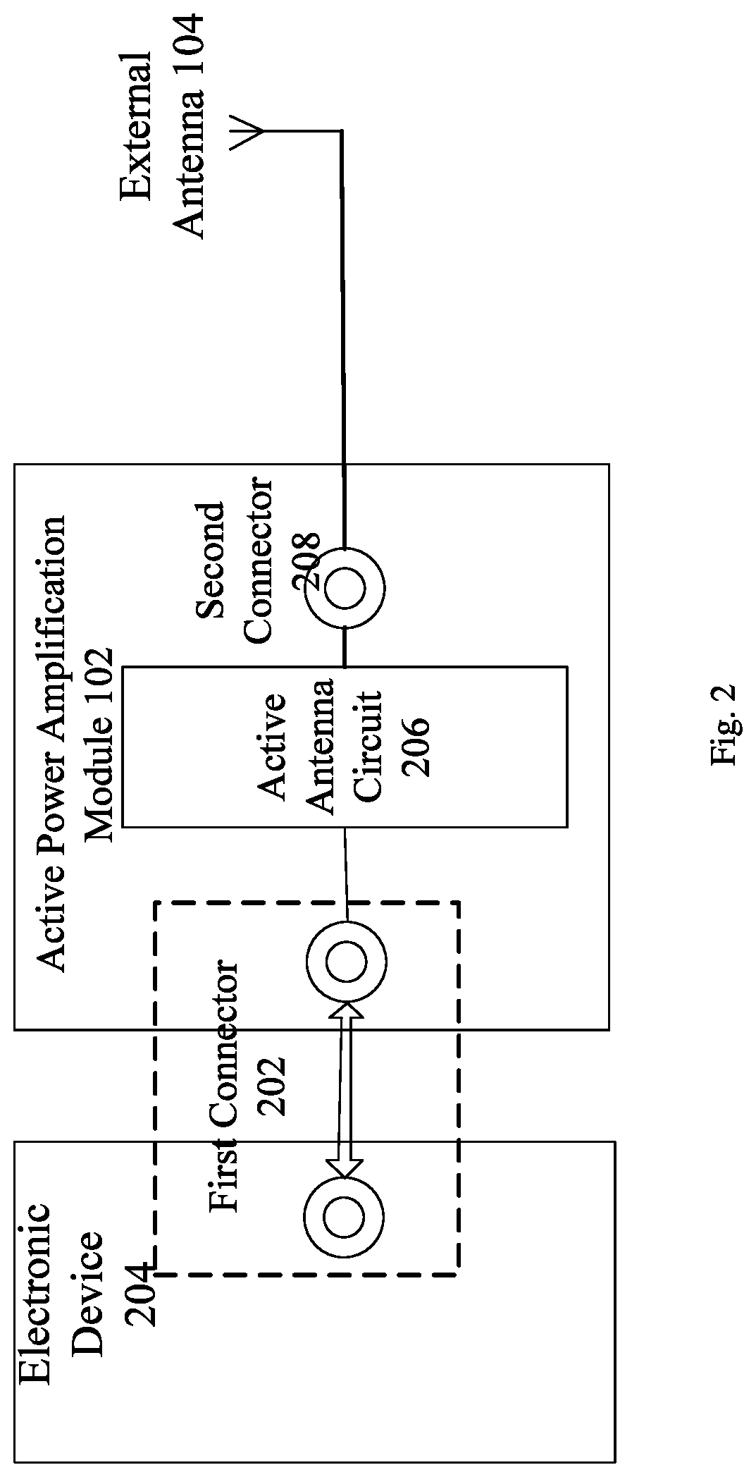
[0043]1) the active power amplifier 102 is detachably electrically coupled to an electronic device, wherein the active power amplifier comprises an active antenna circuit for amplifying and filtering a signal; and

[0044]2) the external antenna 104 is detachably electrically coupled to the active power amplifier.

[0045]Alternatively, in this embodiment, the active antenna system may be applied, but not limited, to ...

embodiment 2

[0111]In this embodiment, a mobile terminal for implementing the above embodiments and preferred implementations is further provided, and those that have been illustrated as above will be omitted herein. As used below, the term “unit” may implement a combination of software and / or hardware of predetermined functions. Although the devices described in the following embodiments are preferably implemented through software, hardware or a combination of software and hardware are also possible and contemplated.

[0112]FIG. 9 is a block diagram showing a structure of a mobile terminal according to an embodiment of the present disclosure. As shown in FIG. 9, the mobile terminal device comprises a mobile terminal entity 902 and an active antenna system 904, wherein the active antenna system is detachably coupled to the mobile terminal entity via a connector 906.

[0113]It should be noted that, in this embodiment, the active antenna system is detachably coupled to the mobile terminal entity as an...

embodiment 3

[0149]In this embodiment, a configuration method of an antenna system for applying to a mobile terminal is further provided. As shown in FIG. 10, the method comprises steps of:

[0150]in step S1002, the antenna detecting unit detects a voltage level state of a detection point, and returns a level signal corresponding to a detected result to a baseband unit;

[0151]in step S1004, the baseband unit determines whether a current antenna is an internal passive antenna, an external passive antenna, or an external active antenna based on the detected result of the antenna detecting unit, and outputs corresponding control information to the antenna tuning unit; and the antenna tuning unit configures corresponding antenna parameters according to the control information;

[0152]in step S1006, the baseband unit outputs the corresponding control signal to a unit of the radio frequency circuit for configuring a working status of the radio frequency circuit.

[0153]Alternatively, in this embodiment, said...


PUM


Abstract

Provided are an active antenna system, a mobile terminal, and a configuration method of an antenna system. The active antenna system includes an active amplification module and an external antenna. The active amplification module is detachably electrically coupled to an electronic device, wherein the active power amplification module includes an active antenna circuit for amplifying and filtering a signal transmitted and received by the external antenna, and the external antenna is detachably electrically coupled to the active power amplification module. The problem of increase of power consumption of the terminal caused by enlarging a signal radiation range of the terminal is solved, thereby realizing decrease of the power consumption of the terminal while enlarging the signal radiation range of the terminal.

Description

FIELD OF THE INVENTION[0001]The present disclosure relates to the technical field of communication, and in particular, to an active antenna system, a mobile terminal, and a configuration method of an antenna system.BACKGROUND OF THE INVENTION[0002]With rapid development of communication technology, people's demands for data throughput of mobile terminals are increasingly promoted, and higher and higher requirements for miniaturization and portability of wireless communication products are also put forward in the meanwhile. It is hoped that the terminal will have a slimmer and more stylish appearance while maintaining its advanced performance (a broader signal radiation range, and higher system receiving sensitivity). In order to meet consumer demand for small wireless devices, the available space of a mobile terminal antenna is getting smaller and smaller, but it is difficult to design a compact antenna that works desirably in a wide frequency range. It is easier to realize antenna ...

Claims


Application Information

Patent Timeline
Patent Type & Authority Patents(United States)
IPC IPC(8): H04B7/005H04W52/30H04W52/02H04B1/525H04M1/02H01Q1/24H04B1/44H04B7/26H04L5/14H04B1/04H04W52/52
CPCH04W52/30H01Q1/247H04B1/44H04B1/525H04B7/2643H04L5/143H04L5/1461H04M1/02H04W52/02H04B2001/0408H04W52/52Y02D30/70H04W52/0267
Inventor NIU, HUI
Owner ZTE CORP
Why Eureka
Try Eureka