
Radial artery compression band having fine adjustment mechanism

a compression band and radial artery technology, applied in the field of compression band of radial artery, can solve the problems of hand pain, numbness, and radial artery collapse when applying pressure, and achieve the effect of facilitating manual rotation

Active Publication Date: 2021-02-16
OSCOR
View PDF15 Cites 1 Cited by
  • Summary
  • Abstract
  • Description
  • Claims
  • Application Information

AI Technical Summary

Benefits of technology

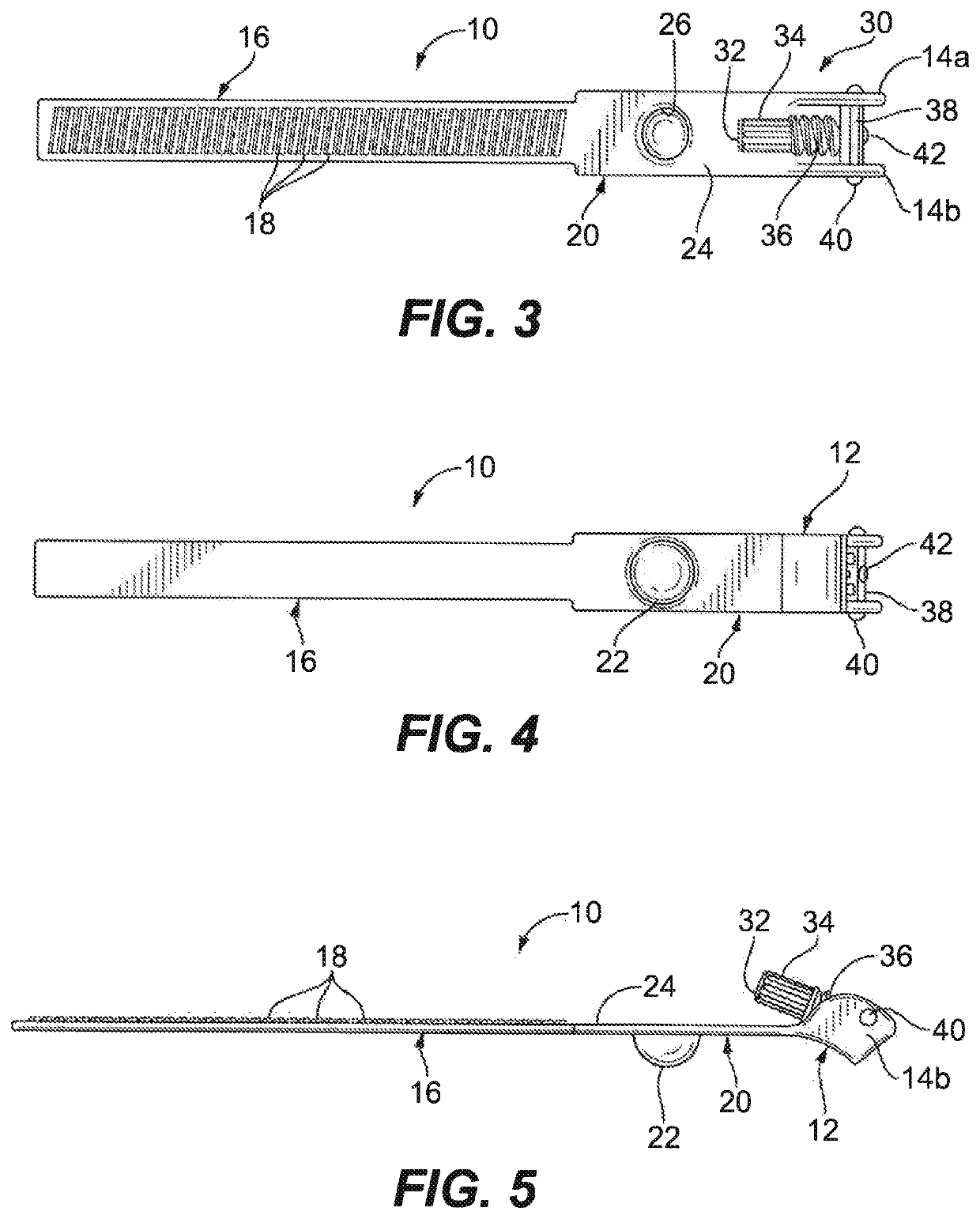
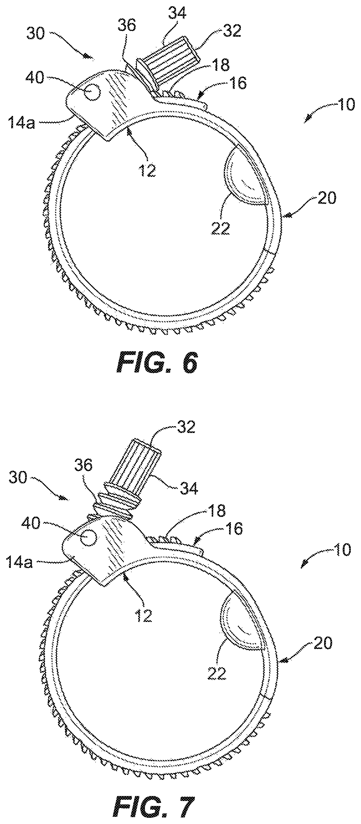
[0008]Preferably, the band adjustment mechanism includes an over-centered latch member that is pivotably mounted to the support frame about a transverse pivot axis, and the support frame includes a pair of laterally spaced apart upstanding walls that pivotably support the over-centered latch member of the band adjustment mechanism therebetween. The axially rotatable shaft is rotatably connected to the over-centered latch member by a threaded fastener, and it includes a knurled handle section to facilitate manual rotation of the worm gear section of the shaft relative to the engagement teeth of the second band portion.

Problems solved by technology

However, certain deficiencies exist with respect to conventional devices used to provide hemostasis of a radial access site.
For instance, conventional hemostasis devices (including compression bands), while being able to provide the necessary pressure to achieve hemostasis, are known to collapse the radial artery when applying pressure.
Occlusion of the radial artery can restrict adequate blood supply to the hand, causing complications such as pain and numbness in the hand.

Method used


Image

  • Radial artery compression band having fine adjustment mechanism
  • Radial artery compression band having fine adjustment mechanism
  • Radial artery compression band having fine adjustment mechanism

Examples


Embodiment Construction

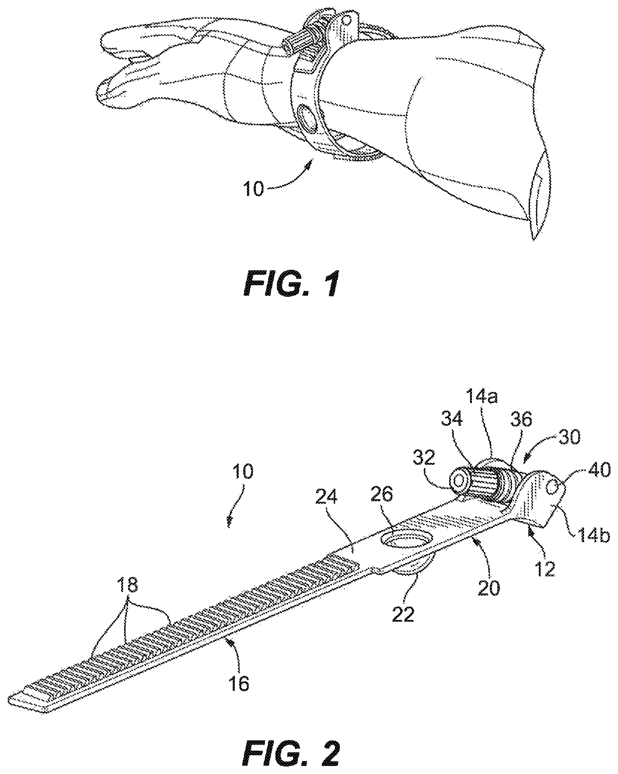
[0023]Referring now to the drawings, wherein like reference numerals identify similar structural elements of the subject invention, there is illustrated in FIG. 1 a new and useful compression band 10 for circumferential placement around the wrist of a patient to apply hemostasis pressure to a surface wound, and thereby constrict blood loss following a radial artery intervention procedure.

[0024]More particularly, the compression band 10 of the subject invention is adapted and configured to provide a means for precisely adjusting pressure applied to a radial artery wound on a patient's wrist, while monitoring the patient's pulse rate with an oximeter on their finger to confirm the proper blood flow past the radial artery wound to the hand. In addition, the compression band 10 is designed to precisely adjust the pressure applied to the wound so as to prevent clotting in the artery and promote the natural healing of the wound.

[0025]Referring now to FIGS. 2 through 5, the compression ban...


PUM


Abstract

A radial artery compression band is disclosed for circumferential placement around the wrist of a patient to apply hemostasis pressure to a wound, which includes a first arcuate band portion including a radially outwardly extending support frame, a second elongated band portion including a plurality of longitudinally spaced apart radially outwardly extending ramped engagement teeth, a third elongated band portion extending between the first and second band portions and including a radially inwardly facing compression structure for applying hemostasis pressure to the wound, and a band adjustment mechanism mounted within the support frame of the first arcuate band portion and including an axially rotatable shaft having a worm gear section with a continuous helical thread for selectively intermeshing with the ramped engagement teeth on the second elongated band portion to adjust band tension through axial rotation of the shaft.

Description

BACKGROUND OF THE INVENTION1. Field of the Invention[0001]The subject invention is directed to a compressive hemostatic device, and more particularly, to a radial artery compression band for precisely applying hemostasis pressure to a vascular intervention site following a radial artery procedure.2. Description of Related Art[0002]Vascular intervention procedures have long been performed by accessing the femoral artery. However, access of the radial artery has become accepted as an alternative to femoral artery intervention for certain intervention procedures. For example, radial artery access for cardiac catheterization has become an accepted intervention procedure. Indeed, it has been found that intervention of the radial artery reduces costs and potential complications when compared to femoral artery invention.[0003]Following the intervention, hemostasis of the access site is achieved by applying a hemostasis compression band to the site or by applying manual pressure to the site...

Claims


Application Information

Patent Timeline
Patent Type & Authority Patents(United States)
IPC IPC(8): A61B17/132A61B17/12
CPCA61B17/1327A61B2017/12004A61B17/1325
Inventor SEARFOSS, TIMOTHYOSYPKA, THOMAS P.
Owner OSCOR
Learn More