Energy storage and recovery system

a technology of energy storage and recovery system, applied in the direction of propulsion parts, transportation and packaging, gas pressure propulsion mounting, etc., can solve the problems of low power (or even engine braking) at other points in the cycle, and achieve the effect of improving the efficiency of energy transfer transmission, reducing the size of prime mover, and efficient and/or reducing the siz

Active Publication Date: 2021-02-23
PUNCH FLYBRID LTD
View PDF13 Cites 0 Cited by
  • Summary
  • Abstract
  • Description
  • Claims
  • Application Information

AI Technical Summary

Benefits of technology

[0009]An aim of this invention is to improve the efficiency of an energy transfer transmission in an ERS for a vehicle or a machine such as a construction, industrial, agricultural or other off-highway vehicle or machine. A further aim of this invention is to provide an ERS which can enable an efficient and / or a reduced size prime mover in a vehicle or a machine such as a construction, industrial, agricultural or other off-highway vehicle or machine. A further aim of this invention is to provide a plurality of modes of ERS operation in a vehicle or a machine such as a construction, industrial, agricultural or other off-highway vehicle or machine, with the aim of reducing system cost and / or fuel consumption and / or exhaust emissions. A further aim of this invention is to provide a low technical risk, low cost and compact ERS for use in a vehicle or a machine such as a construction, industrial, agricultural or other off-highway vehicle or machine.

Problems solved by technology

In certain applications where cyclic, frequently repeated, operations are required to be carried out, the engine can be operating at certain points in the repeated cycle, but very low power (or even engine braking) at other points in the cycle.

Method used


Image

  • Energy storage and recovery system
  • Energy storage and recovery system
  • Energy storage and recovery system

Examples


Embodiment Construction

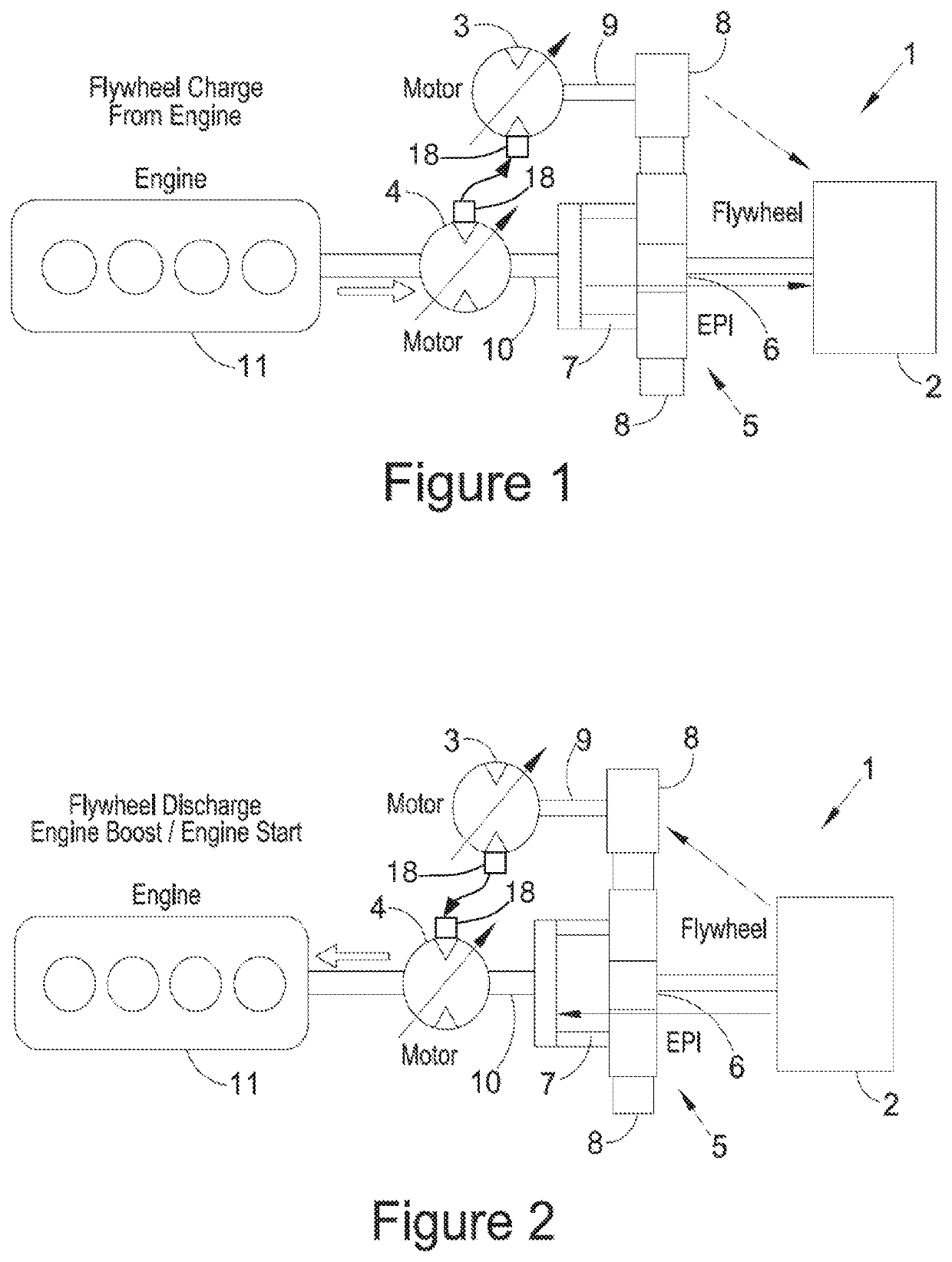
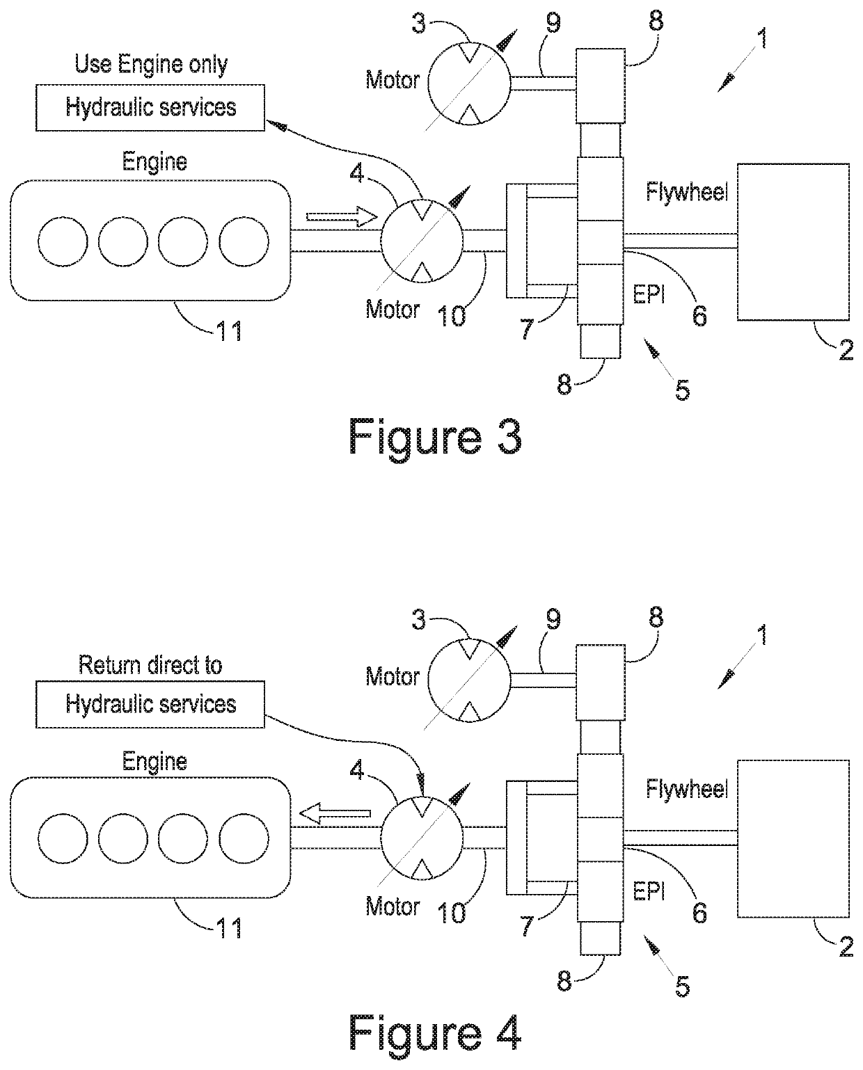
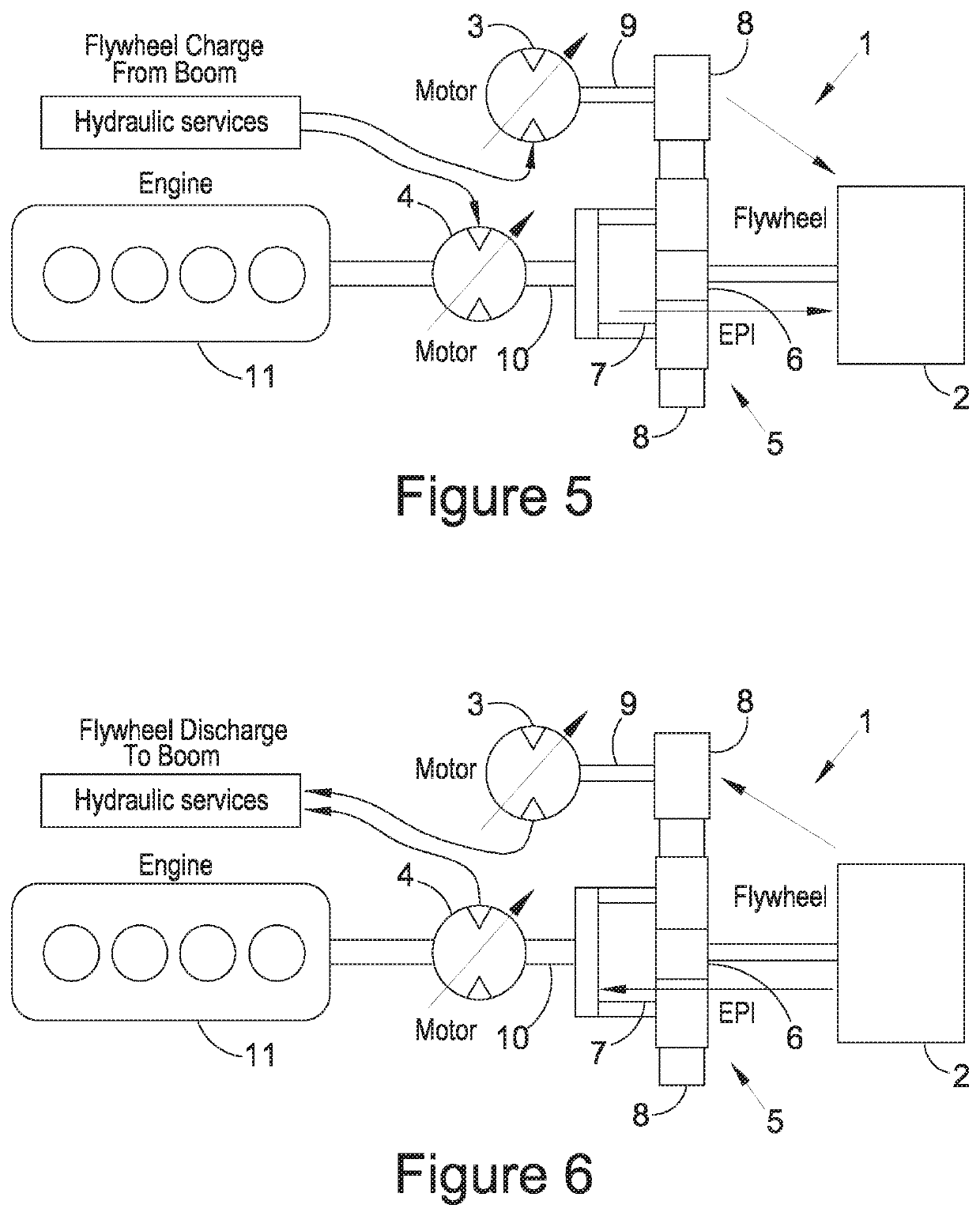
[0081]With reference to FIGS. 1 to 6, an engine (or other prime mover) 11 is coupled to a first pumping element 4 which has an associated driveshaft 10 coupled to the carrier 7 of a simple epicyclic gearset 5. A second pumping element 3 which has an associated driveshaft 9 is coupled via a gear to an annulus 8 of epicyclic 5. A sun 6 is coupled to flywheel 2.

[0082]FIG. 1 shows the case where the first pumping element 4 is coupled to second pumping element 3, their respective fluid coupling arrangements arranged for transfer of fluid at pressure, and hence hydrostatic power, between them. By varying the displacement of one or both pumping elements using the fluid displacement mechanism 18, the CVT ratio can be adjusted in order to drive power into the flywheel. In this example, the torque applied to the carrier 7 will be opposite to that applied to the annulus 8. Hence in order to transfer power in a parallel fashion, as required by a power-split arrangement, the annulus should be dr...


PUM


Abstract

The invention relates to an energy storage and recovery system (ERS) coupleable to a prime mover and to an energy storage flywheel. The ERS has a hydrostatic arrangement with a first pumping element and a second pumping element. The pumping elements have a respective fluid displacement and a fluid coupling arrangement for the transfer of fluid power between the first and second pumping elements. The ERS also includes a differential device comprising at least three inputs, wherein a first driveshaft of the first pumping element is coupled to a prime mover in use, a first input of the a differential device is coupled to said prime mover in use, a second input of the differential device is coupled to a second driveshaft of the second pumping element, and the third input of the differential device is coupled to a flywheel in use.

Description

CROSS-REFERENCE TO RELATED APPLICATIONS[0001]The present application claims priority to PCT International Application No. PCT / GB2018 / 050288 filed on Jan. 31, 2018, which claims priority to GB 1701610.6 filed Jan. 31, 2017, the entirety of the disclosures of which are expressly incorporated herein by reference.STATEMENT RE: FEDERALLY SPONSORED RESEARCH / DEVELOPMENT[0002]Not Applicable.FIELD OF THE INVENTION[0003]The present invention relates to an energy recovery system (ERS) and in particular, to a KERS in which energy is stored as rotational kinetic energy in a flywheel. The invention has particular, but not exclusive, application to construction, industrial, agricultural and other off-highway vehicles, but also has application of other vehicles and machines. The abbreviation “ERS” will be used to refer to an energy recovery system.BACKGROUND OF THE INVENTION[0004]It is known to attach an ERS to a part of vehicle drivetrain. An ERS comprises typically a flywheel system and an energy...

Claims


Application Information

Patent Timeline
Patent Type & Authority Patents(United States)
IPC IPC(8): B60K6/10B60L50/30B60K6/30B60K6/365B60K25/02
CPCB60K6/105B60K6/30B60K6/365B60K25/02B60L50/30Y02T10/62Y02T10/70B60K6/36
Inventor DEAKIN, ANDREW
Owner PUNCH FLYBRID LTD
Why Eureka
Try Eureka