
Eccentric bicycle fork shaft

a bicycle and bending technology, applied in the field of bicycle forks, can solve the problems of reduced mechanical stability reduced bending stiffness, and inability to guide the mechanical gear shift cable in an entirely integrated (internalized) manner, and achieves a high degree of flexibility and high bending stiffness of the fork sha

Active Publication Date: 2021-02-23
SCOTT SPORTS
View PDF16 Cites 4 Cited by
  • Summary
  • Abstract
  • Description
  • Claims
  • Application Information

AI Technical Summary

Benefits of technology

[0011]It is therefore one non-limiting object of the present teachings to discloses disclose an integrated (internalized) guiding of brake and / or gear shift cables, which, e.g., ensures a high bending stiffness of the fork shaft, the usage of inexpensive, standardized components and / or a high degree of flexibility with respect to the adjustment of the height of the handlebar stem on the fork shaft.
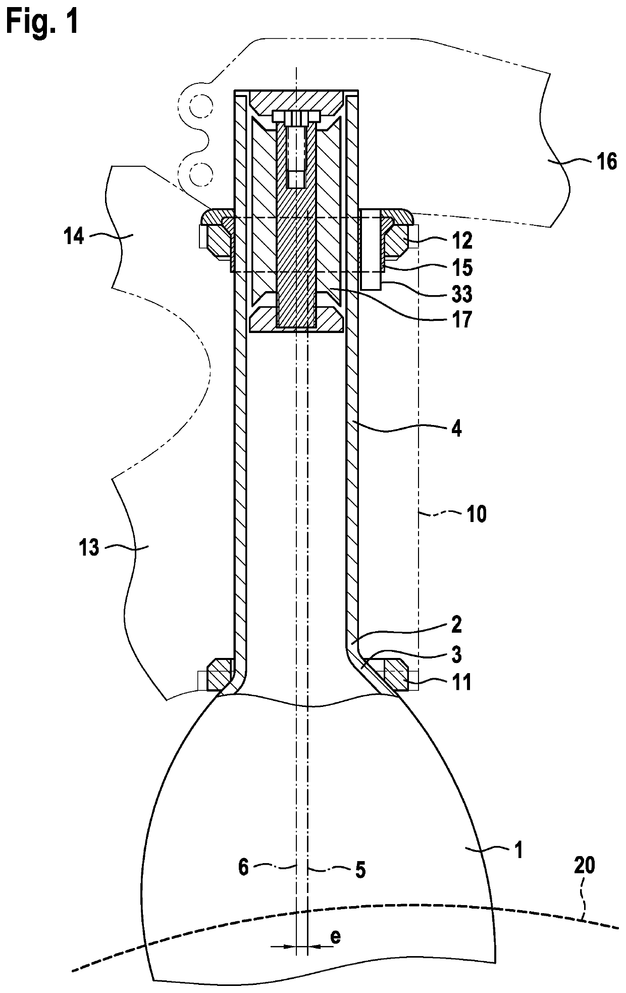
[0017]It is noted that a maximum lateral bending stiffness can be ensured by the cylindrical shape of the fork shaft and / or by its circular outer cross section.
[0018]Preferably, the cylindrical fork shaft segment has not only a cylindrical outer side, but also has a cylindrical inner side, i.e. it is hollow inside, has a circular inner cross section perpendicular to the fork shaft axis with a preferably constant wall thickness, so that a low-cost standard eccentric component can be fixed in the interior of the fork shaft. Accordingly, usage of a specially shaped expander component is not necessary.
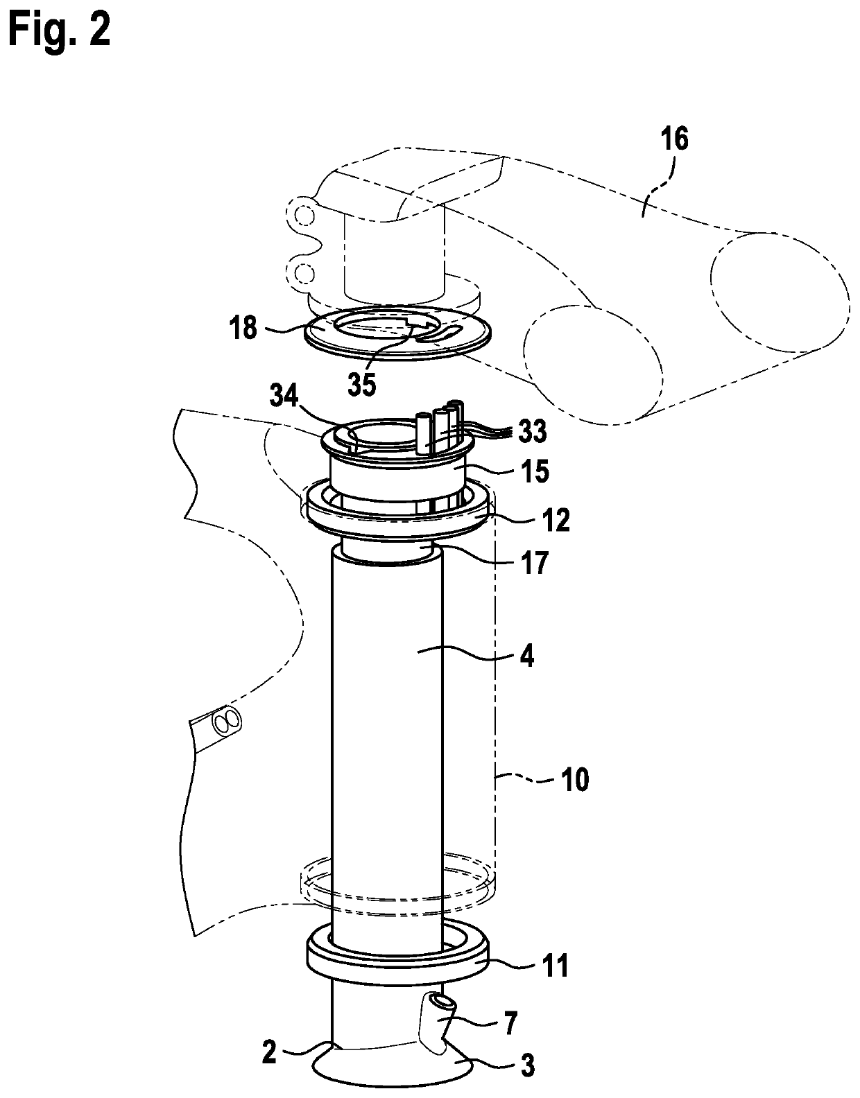
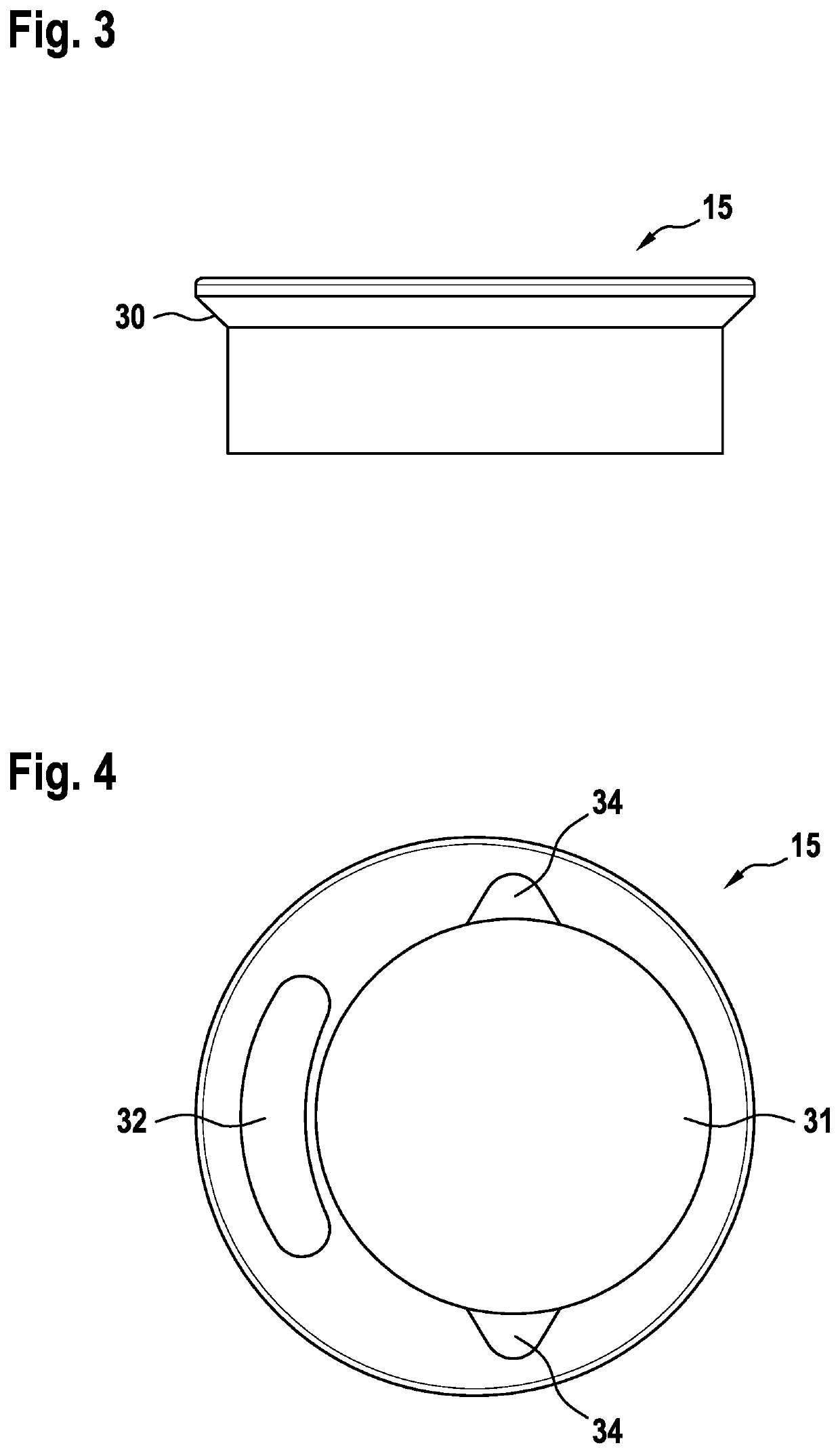
[0025]Further, the reduction sleeve preferably comprises a continuous, preferably elongated guide window for brake and / or gear shift cables or their sheaths, wherein the guide window is preferably configured for guiding-through (holding) four cables or cable sheaths, particularly preferably for guiding-through (holding) the cable sheaths of two brake cables and two gear shift cables. In this case, the guide window is disposed between the circular through-hole and the engaging segment, so that four cable sheaths can be guided-through (held) between the fork shaft and the upper headset bearing, wherein the cable sheaths preferably extend side by side and / or directly abutting one another. In this case, when passed through the guide window, the four cables or cable sheaths point in the direction, or substantially in the direction, of the fork shaft axis and / or the steering axis, i.e. they extend parallel or substantially parallel to the fork shaft axis and the steering axis. In this case, it also is provided that mechanical cables, which are protected and / or guided by corresponding cable sheaths, can be guided through the upper headset bearing along the fork shaft, through the guide window. This increases the mechanical protection of the cables, minimizes friction losses and accordingly facilitates precise gear shifting and / or braking.
[0029]Further, a cable stop for one or more, in particular for two or three, mechanical gear shift and / or brake cables is preferably provided in the lower tube of the bicycle frame. In this case, the cable sheaths of the mechanical gear shift and / or brake cables, after passing through the reduction sleeve and the head tube, end at the cable stop in the lower tube, and the mechanical cables can be guided in the interior of the bicycle frame, at least partially or completely, without cable sheaths toward the bottom bracket and / or the rear wheel. In this case, the cable stop is preferably attached at a front end or in the upper third of the lower tube, in particular at a distance of 2 to 20 cm from the steering axis, for example 2, 5, 10, 15 or 20 cm, wherein each of the mentioned values can also be an upper or lower limit of the mentioned range of values. The provision of such a cable stop in the vicinity of the head tube makes it possible to minimize the region (length or extension), in which the mechanical shift cables are guided through the respective cable sheaths, and accordingly to reduce the overall weight of the bicycle frame and thus of the bicycle.
[0033]Preferably, the headsets in the bicycle frame comprise exclusively standard components, whereby the component costs can be minimized. The present teachings further concern a bicycle, e.g., a racing bicycle, comprising a bicycle frame as described above and / or a bicycle fork as described above.

Problems solved by technology

However, this flattening leads to a reduced mechanical stability of the fork shaft (for example, to a reduction of the bending stiffness or the second-order moment of resistance) and, moreover, requires the usage of a special expander component that fits into the now non-circular or non-cylindrical inner side of the flattened fork shaft.
In addition, the vacant installation space created therein is too small in any event to guide (hold) all four cables (for example two mechanical brake cables and two mechanical gear shift cables), so that for example mechanical gear shift cables cannot be guided in entirely integrated (internalized) manner.
Further, tight radii of deflection are realized in this case, which results in high frictional losses in mechanical cables and correspondingly imprecise shifting and / or braking, in particular when the cables are guided without a cable sheath.

Method used


Image

  • Eccentric bicycle fork shaft
  • Eccentric bicycle fork shaft
  • Eccentric bicycle fork shaft

Examples


embodiment 1

[0052]2. The bicycle fork (1) , characterized in that the cylindrical fork shaft segment (4) forms the uppermost segment and / or the upper end of the fork shaft (2).

[0053]3. The bicycle fork (1) according to embodiment 1 or 2, characterized in that the cylindrical fork shaft segment (4) has a fork shaft axis (6) that extends within a symmetry plane of the bicycle fork and / or extends parallel to the steering axis (5), is spaced apart from the steering axis and is offset with respect to the steering axis in a direction of eccentricity by an eccentric distance (e), preferably by 1 to 5 mm, particularly preferably by 3 mm, wherein the direction of eccentricity preferably points opposite to the direction of travel.

[0054]4. The bicycle fork (1) according to any of the preceding embodiments, characterized in that the cylindrical fork shaft segment (4) has a hollow interior with a cylindrical inner side.

[0055]5. The bicycle fork (1) according to any of the preceding embodiments, characterize...

embodiment 5

[0056]6. The bicycle fork (1) , characterized in that the cone of the tapered fork shaft segment has a circular outer cross section in a plane perpendicular to the steering axis (5) and / or to the fork shaft axis (6), the circle center point of said circular outer cross section coinciding with the steering axis.

[0057]7. The bicycle fork (1) according to any of the preceding embodiments, characterized in that, along the fork shaft axis and / or steering axis (5, 6), the height of the fork shaft (2) amounts to 100 to 400 mm and / or the height of the engaging segment (3) amounts to 3 to 10 mm, preferably 5 mm, and / or the height of the cylindrical fork shaft segment (4) amounts to 90 to 397 mm.

[0058]8. The bicycle fork (1) according to any of the preceding embodiments, characterized in that the fork shaft (2) consists of the engaging segment (3), the cylindrical fork shaft segment (4) and preferably a feed-through opening (7) for the brake cable of the front wheel brake.

[0059]9. The bicycle...

embodiment 12

[0063]13. The bicycle frame , characterized in that the cylindrical fork shaft segment (4) has a smaller outer diameter than the inside measurement of the upper headset bearing (12).

[0064]14. The bicycle frame according to embodiment 12 or 13, characterized in that the cylindrical fork shaft segment (4) extends through the upper headset bearing (12).

[0065]15. The bicycle frame according to any of embodiments 12 to 14, further comprising a reduction sleeve (15) that engages on the cylindrical fork shaft segment (4) and the upper headset bearing (12).


PUM


Abstract

A bicycle fork includes a fork shaft configured to be rotatably borne by headset bearings in a head tube of a bicycle frame so as to rotate about a steering axis. The fork shaft includes a cylindrical fork shaft segment that is disposed eccentrically with respect to the steering axis. The cylindrical fork shaft segment is a right circular cylinder having a hollow interior, a cylindrical inner surface and a central longitudinal axis that lies within a symmetry plane of the bicycle frame and extends parallel to the steering axis. The central longitudinal axis of the cylindrical fork shaft segment is spaced apart from the steering axis in a direction of eccentricity that points in an opposite direction with respect to a forward direction of travel of the bicycle.

Description

CROSS-REFERENCE TO RELATED APPLICATION[0001]This application claims priority to German utility model application no. 20 2017 004 993.7 filed on Sep. 26, 2017, the contents of which are fully incorporated herein by reference.TECHNICAL FIELD[0002]The present invention relates to a bicycle fork, a bicycle frame having a bicycle fork and a corresponding bicycle.BACKGROUND[0003]In bicycles steering impulses induced on the handlebar are transferred via a handlebar stem and further, via a force- and friction-fit, rotationally rigid connection, to the fork shaft of a bicycle fork, which holds a front wheel. For this purpose, the fork shaft of the bicycle fork is borne in a head tube of the bicycle frame so as to be rotatable about a steering- or control axis. This is usually done with the aid of two headset bearings, which are respectively disposed at the upper end and the lower end of the head tube and which determine the steering axis. Also the upper and lower tubes of the bicycle frame t...

Claims


Application Information

Patent Timeline
Patent Type & Authority Patents(United States)
IPC IPC(8): B62K21/02B62J99/00B62K19/32B62K21/06B62K21/18B62J11/13
CPCB62K21/02B62J99/00B62K19/32B62K21/06B62K21/18B62J11/13
Inventor SÜSSE, RICCO
Owner SCOTT SPORTS
Learn More