External vents

a technology of external vents and vents, applied in the field of external vents, can solve problems such as damage to interior structures or other problems, and achieve the effects of enhancing flow performance, superior flashing, and superior resistance to sunlight and uv degradation

Active Publication Date: 2021-02-23
LIFETIME TOOL & BUILDING PROD
View PDF3 Cites 0 Cited by
  • Summary
  • Abstract
  • Description
  • Claims
  • Application Information

AI Technical Summary

Benefits of technology

[0006]The new vent provides superior flashing, allowing application to a metal roof or interleaving within the shingled roof, creating true water shedding, a watertight seal preventing ingress of pooled water on the roof from snow accumulation or ice damming, superior resistance to sunlight and UV degradation, and consistently increasing outward flow cross-sectional dimensions enhancing flow performance. Downdraft and ambient wind causing damper rattle are prevented. The invention prevents condensate freeze-up and directs condensate drainage away from functional features and outward onto the roof surface. The new vents provide easy access for periodic cleaning of the exhaust ducts and easy to install bird and rodent prevention. Simple installation is provided with the ability to connect to 3″ or 4″ exhaust conduit / hoses. The new vents are easy to seal and install on metal roof covering material or in shingles. The new vents aesthetically are pleasing when installed and are shaped to shed falling rain or snow and to have low profiles on roofs. The new vents have structure built to last the life of a roof or longer and are cost effective for the contractors and building owners.
[0018]An outer coated steel cap covers the polymer inner cap. Openings in opposite side walls of the outer coated steel cap receive fasteners for the Tinnerman clips. Two fasteners are removed to lift the caps from the support body to clean the vent. A duct connector connects to the downward extending rim inside of the support body. The support body and the upper end of the duct connector are connected by lanced and pressed snap connectors providing a quick permanent connection of the duct connector to the support body. The assembled vent and the duct connector are separated in a compact package and are easily permanently connected by pushing the assembled vent and the duct connector together.
[0021]Both flashings are made of 24 gauge galvanized, primed and KYNAR coated plates. A deep drawn raised center and gasket receiver surround a central opening. A U-shaped EPDM rubber gasket holds a rim of an angled base support body. The gasket and rim are permanently crimped in the gasket receiver. The angle of the support body allows for condensation drainage. Built-in wind walls and EPDM rubber noise dampers eliminate clatter and allow a small amount of warm air flow, helping to prevent freezing in winter.

Problems solved by technology

Current vent devices known in the art have flaws leading to premature failure and leaking, which can result in damage to the interior structure or other problems such as mold and insect or vermin damage.

Method used


Image

  • External vents
  • External vents
  • External vents

Examples


Embodiment Construction

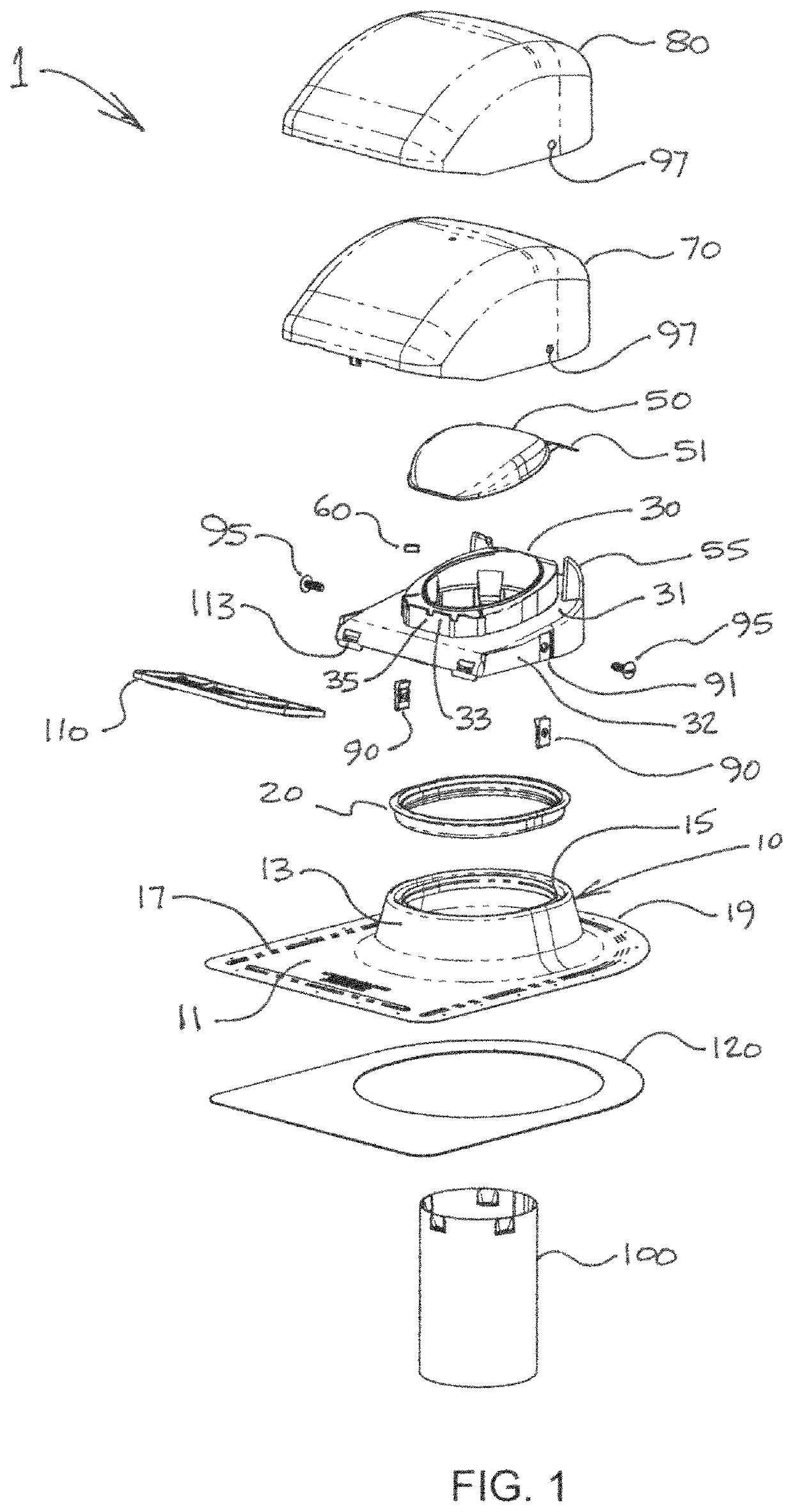
[0041]The new roof vent 1 has a flashing plate base 10 that is large and flat at the bottom 11 and has a deep drawn raised central portion 13 that supports a housing structural body 30 inside a premium acrylonitrile styrene acrylate (ASA) subcap 70 within a galvanized steel KYNAR polyvinylidene fluoride (PVDF) coated outer cap 80. The inner and outer caps are joined to the housing structural body 30 with machine grade marine grade stainless steel clip 90 and black oxide stainless steel screws 95.

[0042]In one embodiment a rectangular large flat bottom has nailing slots at its sides, which are for use on a shingle roof. The slots are replaced with dimples or holes 17 all around for screwing to metal roofs. A duct connector 100 quickly and permanently attaches to the internal housing structure.

[0043]FIG. 1 is an exploded view of the roof vent. The flashing plate 10 is a 24 gauge galvanized, primed and KYNAR-coated plate with screw holes 17 or preparatory dimples along all edges, includ...


PUM


Abstract

A sloped roof vent has a coated steel plate with a raised center and a gasket receiver is formed around a central hole. A structural body is crimped with a gasket in the receiver. The body has an outer wall extending downward over the receiver. A sloping wall extends inward and a vertical wall supports a second sloping wall with an inner rim. A damper staked to an axle covers the rim. Inserts keep the damper from chattering and fully closing. Wind walls prevent outer drafts from lifting the damper. Two fasteners attach caps to the outer wall. Lanced and pressed ledges on a push-in hose connector permanently engage windows on the inner rim of the structural body. A snap-in screen and a hose connector reducer complete a package.

Description

[0001]This application claims the benefit of U.S. Provisional Application No. 62 / 650,104 filed Mar. 29, 2018, which is hereby incorporated by reference in its entirety as if fully set forth herein.BACKGROUND OF THE INVENTION[0002]Venting of exhaust air or gases is required from within the environmentally controlled spaces of a building, such as the powered forced air venting of bathroom spaces to exhaust foul odors and moisture, and such as the powered forced air exhaust from a clothes drying appliance. Another example is the powered forced air exhaust from a kitchen range hood exhausting hot moist air from the cooking surfaces and activity.[0003]In numerous situations it is desirable to provide this ventilation through the roof of a building. Where the gases to be exhausted originate within the building and are forced by fan or other means, a roof exhaust vent placement might provide the shortest length of duct resulting in the least pressure drop and the best performance for the g...

Claims


Application Information

Patent Timeline
Patent Type & Authority Patents(United States)
IPC IPC(8): E04D13/143E04D13/00
CPCE04D13/143E04D13/004E04D13/1476F24F7/02
Inventor CLINE, ROGERMACLEAN-BLEVINS, MARK
Owner LIFETIME TOOL & BUILDING PROD
Why Eureka
Try Eureka