
Selectable force gas generator

a gas generator and preset technology, applied in the direction of ammunition fuzes, weapons, transportation and packaging, etc., can solve the problems of insufficient separation or tumble of the ejection force of the weapon from the aircraft, heavy and reusable conventional bomb rack systems, and high cost, so as to achieve the effect of increasing the outer pressur

Active Publication Date: 2021-03-02
US GOVERNMENT REPRESENTED BY SEC OF THE AIR FORCE
View PDF10 Cites 0 Cited by
  • Summary
  • Abstract
  • Description
  • Claims
  • Application Information

AI Technical Summary

Benefits of technology

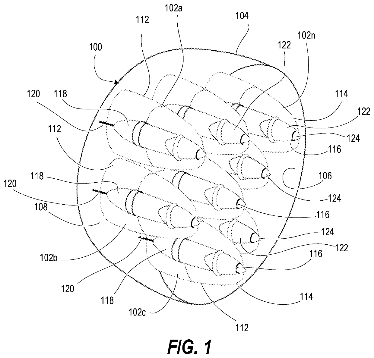
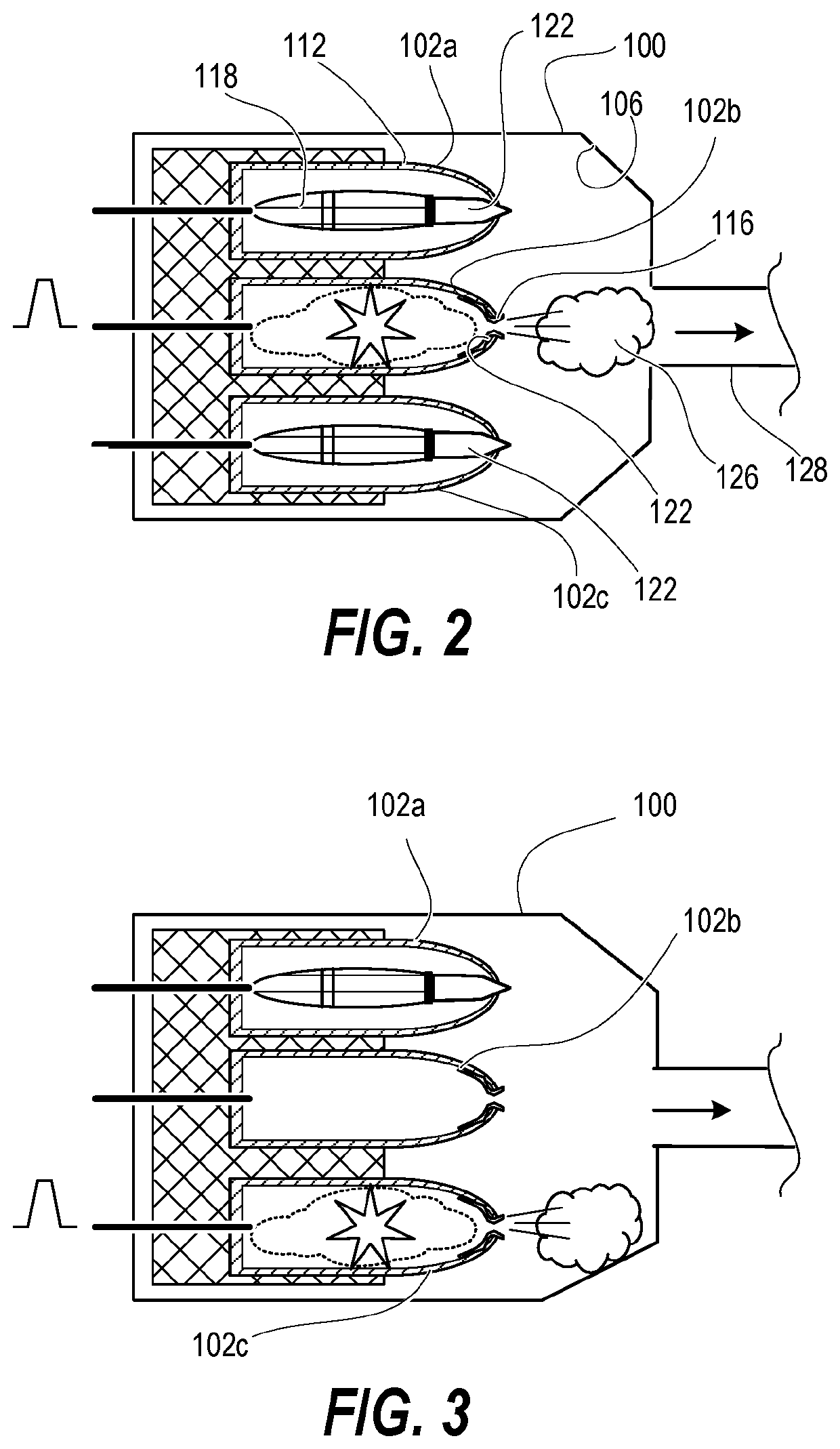
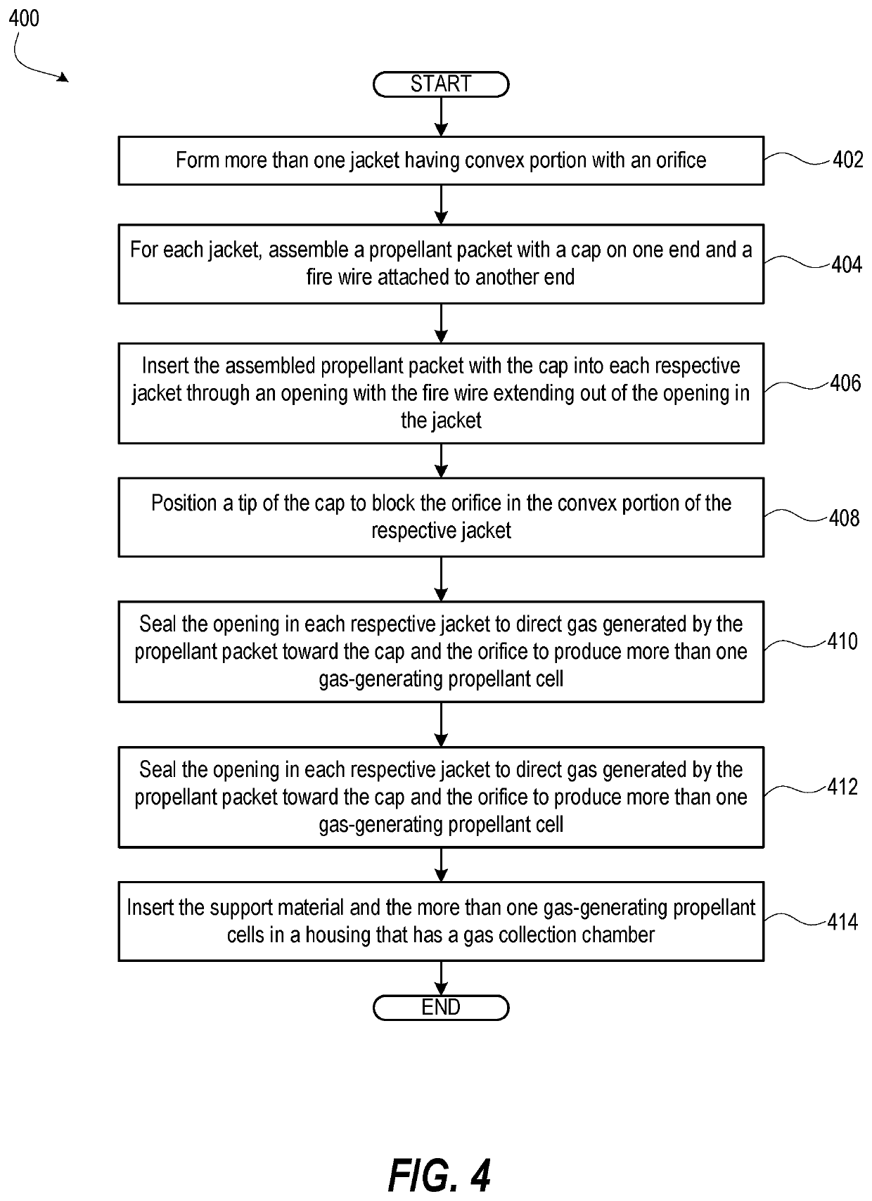
The present patent is about a selectable force gas generator (SFGG) that includes a housing with a gas collection chamber and a fluid-actuated ejector piston. The SFGG contains support material with gas-generating propellant cells that have a steel jacket with a convex portion exposed to the gas collection chamber. Each cell has a fire wire electrically connected to an initiator and the propellant packet. The SFGG also has a cap that blocks the orifice of the jacket to prevent detonation of the propellant packet. The airborne support assembly includes the SFGG and an initiator that supplies a firing signal to activate the gas-generating propellant units. The method of making the SFGG involves forming jackets with an orifice, assembling propellant packets with a cap, and inserting them into the jackets. The SFGG is designed to provide a selectable force to eject the airborne store or to support the aircraft.

Problems solved by technology

Rapid changes in speed, attitude, pitch attitude, pitch rate, sensed gravitational forces, etc., however, can cause a weapon ejected with a preset ejection force to have insufficient separation from the aircraft or to tumble.
In addition, conventional bomb rack system are costly, heavy and reusable which require regular inspections and maintenance.
In addition, they are subject to fatigue, material corrosion, and other long term effects.

Method used


Image

  • Selectable force gas generator
  • Selectable force gas generator
  • Selectable force gas generator

Examples


Embodiment Construction

[0019]According to aspects of the present disclosure,

[0020]The SFGG is an enabling capability for an airborne store support assembly that includes a fluid-actuated ejector piston position a supported airborne store relative to an aircraft and is received for movement in an ejector housing assembly. A selectable force gas generator (SFGG) includes a total number of more than one gas-generating unit in fluid communication with a first ejector housing assembly to actuate the fluid-actuated ejector piston with a selected amount of force. An initiator is in communication with the SFGG and supplies at least one firing signal that causes a selected subset of the more than one gas-generating unit. A first signal switching matrix selectively communicatively couples a firing signal from the initiator to one or more of the gas-generating units. The selected subset corresponds to the selected amount of force that is dynamically determined by a controller based on flight parameters of at least o...


PUM


Abstract

A selectable force gas generator (SFGG) includes support material of honeycomb structure and a gas collection chamber contained in a housing. Gas-generating propellant cells are partially embedded in the support material. Each of the gas-generating propellant cells includes a steel jacket having a convex portion exposed to the gas collection chamber. The steel jacket has an orifice through the convex portion. Each propellant cell includes a propellant packet contained in the jacket. Each propellant cell includes a fire wire electrically connectable to an electrically-fired initiator and electrically connected to the propellant packet. The fire wire transmits a firing signal that causes the propellant packet to produce gas. A cap is positioned between the propellant packet and the jacket. The cap has a tip that blocks the orifice of the jacket and the thickness of the jacket is sufficient to prevent sympathetic detonation of the propellant packet.

Description

[0001]This application is a continuation-in-part patent application to co-pending and commonly owned U.S. patent application Ser. No. 16 / 190,740 entitled “Airborne Store Ejection Using Selectable Force Gas Generator” filed 14 Nov. 2018, which in turn claims the benefit to U.S. Provisional Application Ser. No. 62 / 724,325 entitled “Airborne Store Ejection Using Selectable Force Gas Generator”, filed 29 Sep. 2018, the content of both of which are incorporated herein by reference in their entirety. This application claims the benefit of U.S. Provisional Application Ser. No. 62 / 892,912 entitled “Selectable Force Gas Generator” filed 28 Aug. 2019, the disclosure of which is hereby incorporated by reference in its entirety.ORIGIN OF THE INVENTION[0002]The invention described herein was made by employees of the United States Government and may be manufactured and used by or for the Government of the United States of America for governmental purposes without the payment of any royalties ther...

Claims


Application Information

Patent Timeline
Patent Type & Authority Patents(United States)
IPC IPC(8): F42B3/04F42B3/10B64D1/02F42C19/12
CPCF42B3/04B64D1/02F42B3/10F42C19/12B64D1/04F41F5/00
Inventor PROVENZA, JERRY
Owner US GOVERNMENT REPRESENTED BY SEC OF THE AIR FORCE
Learn More