
Backlights having stacked waveguide and optical components with different coefficients of friction

a waveguide and waveguide technology, applied in the field of light guides, can solve the problems of increasing inventory and cost, high loss of film head-on illumination, moiré artefacts, etc., and achieve the effects of saving power operation, high luminance operation, and large area

Active Publication Date: 2021-03-16
REALD SPARK LLC
View PDF206 Cites 10 Cited by
  • Summary
  • Abstract
  • Description
  • Claims
  • Application Information

AI Technical Summary

Benefits of technology

This patent text describes how a directional backlight can be used to control the brightness and distribution of light emanating from a display. By using an optical waveguide and modulating the brightness of LED light sources, the display can be viewed from a limited range of angles, or with high efficiency and low cost. The text also discusses how the external compressive force can apply to the waveguide to reduce damage and scatter, and to increase the lifetime of the backlight. The technical effects of this invention include reduced costs for controlling the brightness and distribution of light from a display, as well as improved durability and reliability.

Problems solved by technology

However such films have high losses for head-on illumination and the micro-louvres may cause Moiré artefacts due to beating with the pixels of the spatial light modulator.
The pitch of the micro-louvre may need selection for panel resolution, increasing inventory and cost.

Method used


Image

  • Backlights having stacked waveguide and optical components with different coefficients of friction
  • Backlights having stacked waveguide and optical components with different coefficients of friction
  • Backlights having stacked waveguide and optical components with different coefficients of friction

Examples


Embodiment Construction

[0104]It would be desirable to maintain the optical performance of display systems throughout the lifetime of operation of the device incorporating the display. Typically, displays are subjected to compressive forces, for example from operator pressure onto the display (for example by means of a touch screen operation) or during transportation or handling of the device. Such compressive forces may degrade the performance of the display as will now be described. The arrangement of surfaces for an optical stack for a directional display that is resistant to damage from a compressive load will now be described.

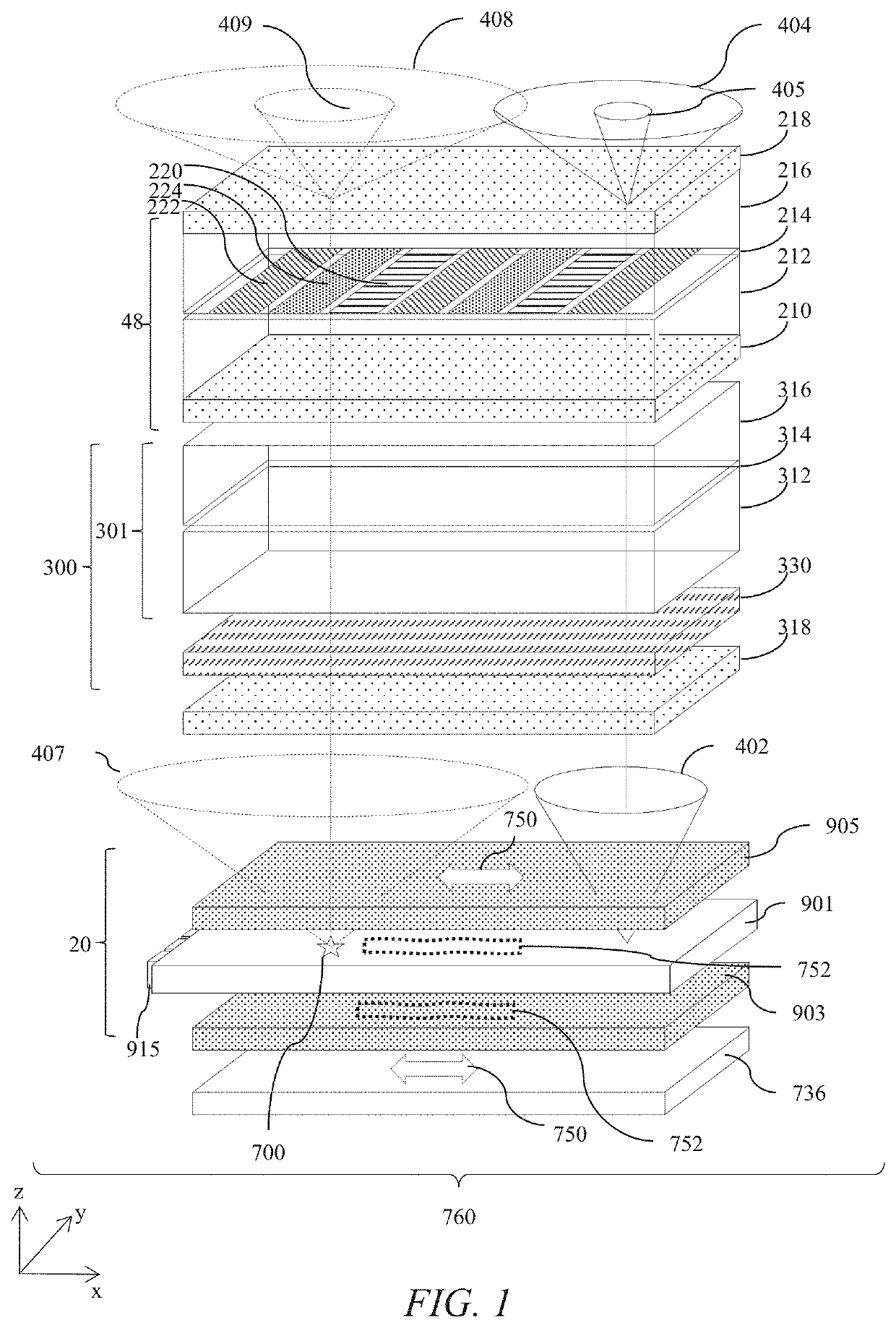
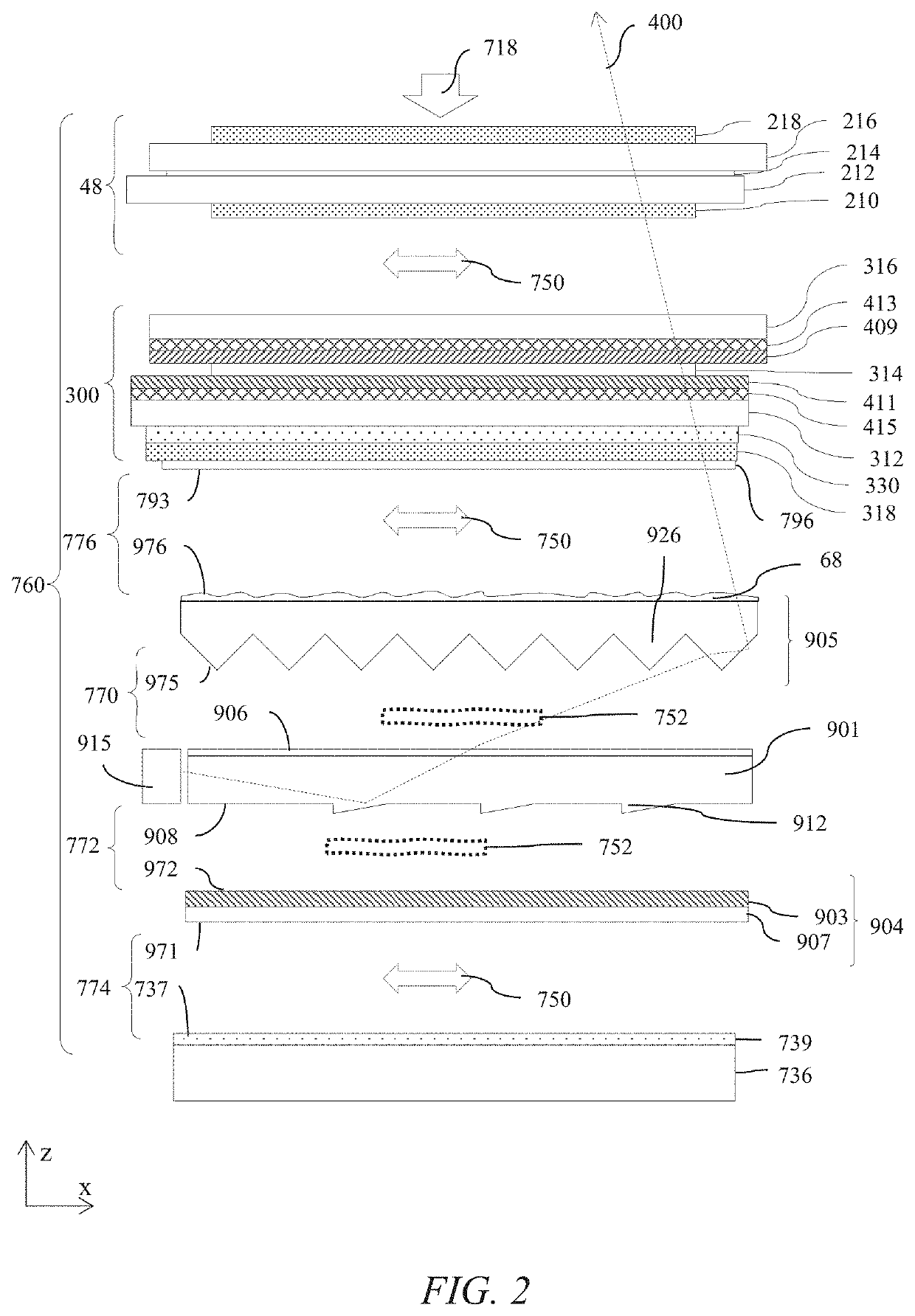
[0105]FIG. 1 is a schematic diagram illustrating in perspective view a directional display optical stack 760 comprising a collimating directional waveguide 901, a switchable retarder 300 and a spatial light modulator 48.

[0106]A directional display device comprises an optical stack 760 comprising a spatial light modulator 48 comprising at least one display polariser that is the ou...


PUM

PropertyMeasurementUnit
RMS roughnessaaaaaaaaaa
water drop contact angleaaaaaaaaaa
heightaaaaaaaaaa

Abstract

A backlight includes a directional waveguide and a light source array, for providing large area directed illumination from localized light sources. Interfaces are provided between the directional waveguide and optical components adjacent the directional waveguide such that the coefficient of friction at the waveguide interfaces is greater than the coefficient of friction at least one outer interface on each side of the waveguide in the stack. Damage from compressive forces on the optical stack may be reduced, achieving improved optical performance and lifetime. Privacy display, low stray light display and autostereoscopic display may be provided with high uniformity, long lifetime and reduced cost mechanical components.

Description

TECHNICAL FIELD[0001]This disclosure generally relates to illumination of light modulation devices, and more specifically relates to light guides for providing large area illumination from localized light sources for use in 2D display including privacy display and low stray light displays, 3D display, and / or autostereoscopic display devices.BACKGROUND[0002]Directional displays provide non-Lambertian luminance distributions to display viewers, that is the luminance varies with viewing direction.[0003]Low stray light displays such as privacy displays provide image visibility to a primary user that is typically in an on-axis position and reduced visibility of image content to a snooper, that is typically in an off-axis position. A privacy function may be provided by micro-louvre optical films that transmit some light from a display in an on-axis direction with low luminance in off-axis positions. However such films have high losses for head-on illumination and the micro-louvres may cau...

Claims


Application Information

Patent Timeline
Patent Type & Authority Patents(United States)
IPC IPC(8): G02F1/13357F21V8/00
CPCG02B6/0046G02B6/005G02B6/0053G02B6/0055G02B6/0088G02B6/0038G02B6/0048G02B6/0051G02B6/0065G02B6/0086
Inventor IHAS, BENJAMINRAMSEY, ROBERT A.WOODGATE, GRAHAM J.HARROLD, JONATHAN
Owner REALD SPARK LLC
Learn More