Chip/dust prevention cover, chip/dust prevention cover set, chuck mechanism, and machine tool
a technology of chip/dust prevention and chip/dust cover, which is applied in the direction of chucks, turning machine accessories, manufacturing tools, etc., can solve the problems of reducing the accuracy of chip attachment, increasing the risk of causing a chucking failure or processing error, and difficulty in completely preventing the intrusion of chips, etc., to achieve high precision and efficiency
- Summary
- Abstract
- Description
- Claims
- Application Information
AI Technical Summary
Benefits of technology
Problems solved by technology
Method used
Image

Examples
first embodiment
[0047]A lathe of an embodiment of the invention which is a first embodiment of the invention will be described with reference to FIGS. 1 to 11.
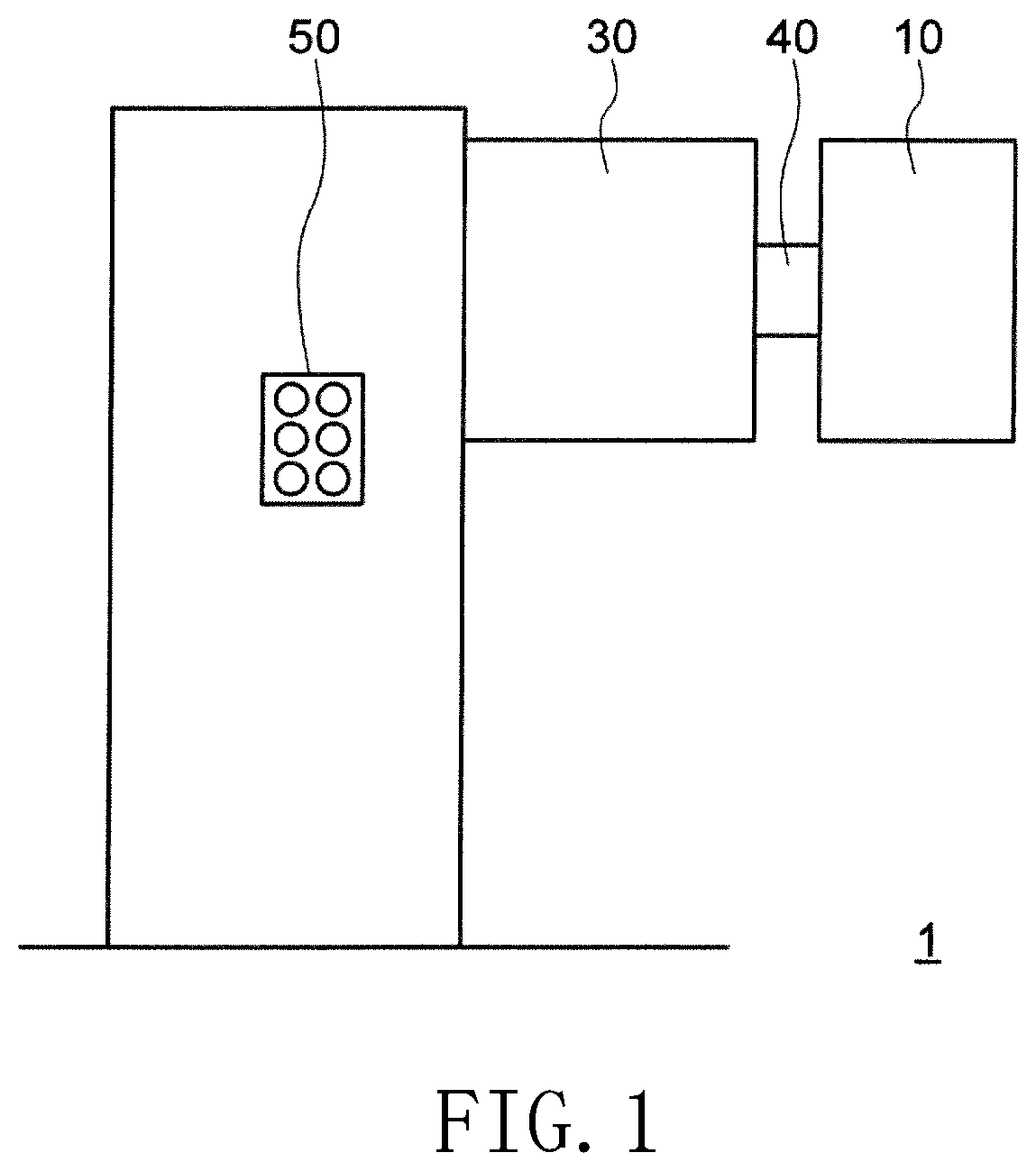
[0048]FIG. 1 is a diagram illustrating a schematic configuration of the lathe of the embodiment of the invention.
[0049]As illustrated in FIG. 1, a lathe 1 of the embodiment includes a chuck mechanism 10 which grips a workpiece corresponding to a processing target, a motor 30 which rotationally drives the chuck mechanism 10, a spindle 40 which transmits rotation power of the motor 30 to the chuck mechanism 10, and a control unit 50 which controls an operation of the motor 30.
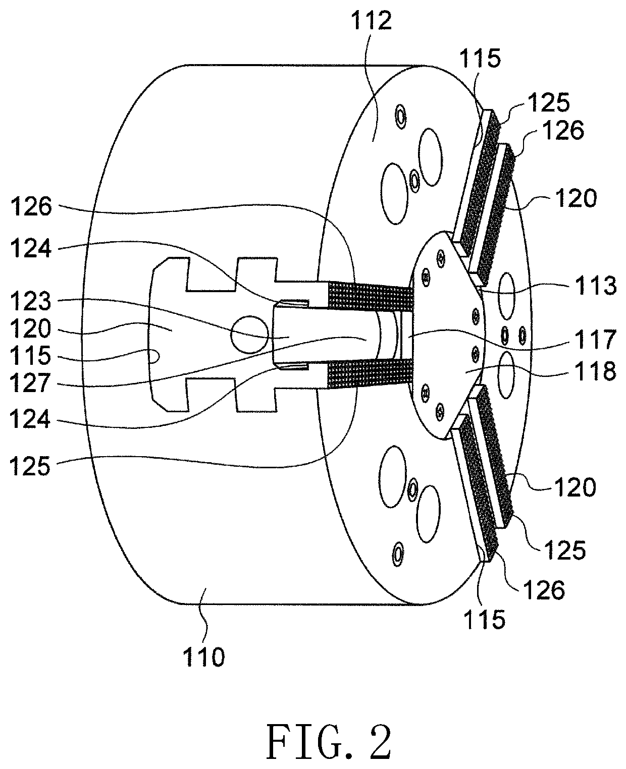
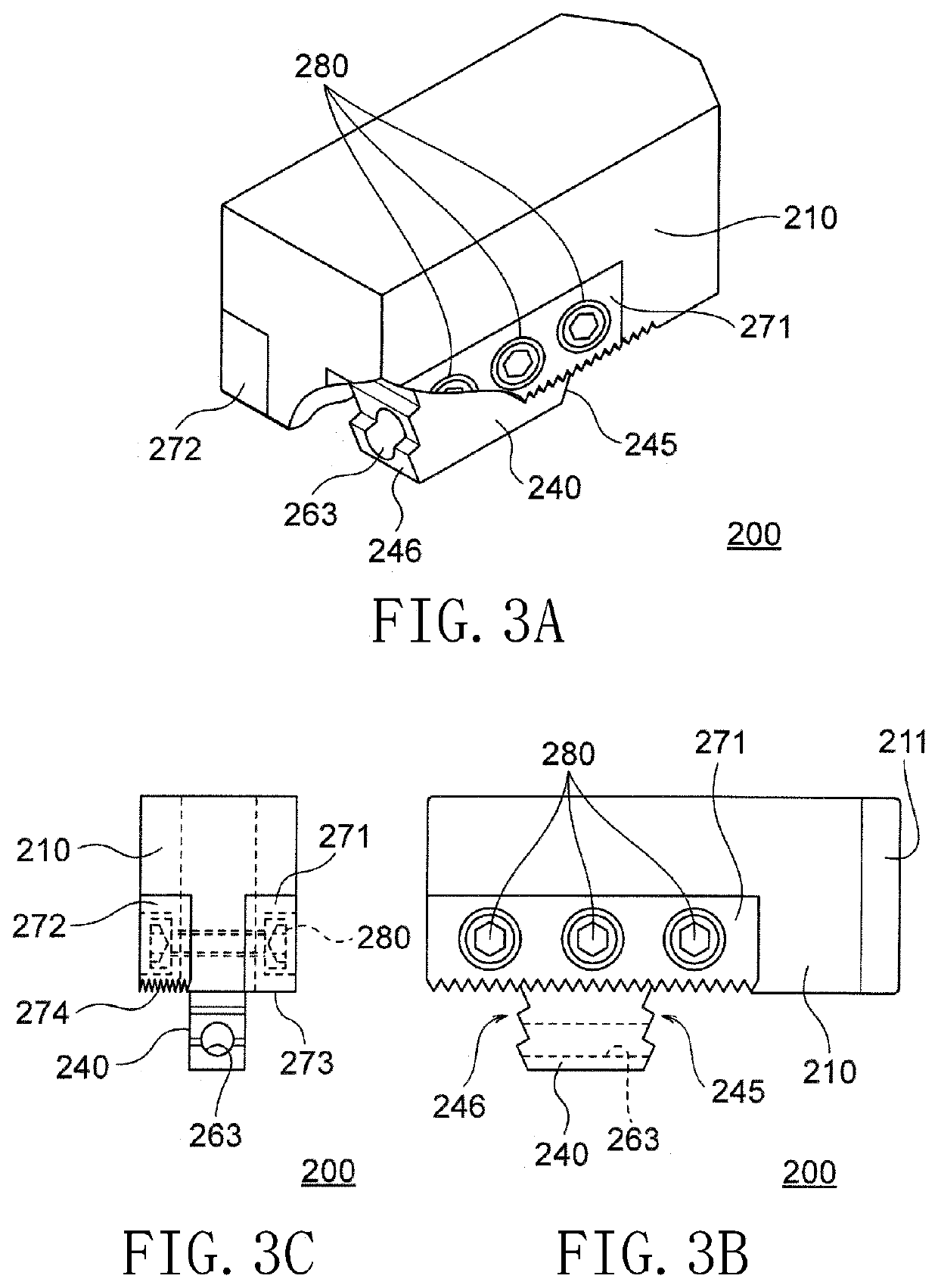
[0050]The chuck mechanism 10 includes a chuck main body 110 and a master jaw 120 illustrated in FIG. 2, a stair form member attached jaw 200 illustrated in FIGS. 3A to 3C, a pair of grips 510 and 540 illustrated in FIGS. 6A and 6B, a top plate 310 illustrated in FIGS. 10A to 10D, and a top cover (chip / dust prevention cover) 360 illustrated in FIGS. 11A to 11C.
[0051]FIG. 2 ...
second embodiment
[0107]Another embodiment of the top cover set (chip / dust prevention cover set) 300 which is a second embodiment of the invention will be described with reference to FIGS. 14 to 16.
[0108]When an automated operation or an unattended operation of a machine tool such as a lathe is performed, it is desirable to perform an air blow for washing on the serration face of the master jaw or the engagement serration face (hereinafter, simply referred to as the serration face 125 of the master jaw) of the master jaw and the soft jaw. A top cover set which is the second embodiment is a top cover set capable of performing an air blow on the serration face of the master jaw.
[0109]Similarly to the top cover set 300 of the first embodiment, the top cover set of the second embodiment also includes one top plate 610 and three top covers (chip / dust prevention covers) 660 and is applied to the lathe 1 which is the same as that of the first embodiment. Here, it is assumed that the chuck main body 110 adop...
modified example
[0133]Furthermore, the invention is not limited to the above-described embodiments and can be arbitrarily modified into various appropriate forms.
[0134]For example, in the above-described embodiments, the master jaw is the master jaw 120 having a cross-sectional shape in which the wide bottom part and the narrow upper part are connected in two stages (see FIG. 2) and the groove 115 of the chuck main body 110 to which the master jaw is fitted also has a cross-sectional shape in which the wide bottom part and the narrow upper part are connected in two stages similarly to the cross-sectional shape of the master jaw 120. However, the structure of the master jaw insertion groove of the chuck main body and the master jaw is not limited thereto. For example, as illustrated in FIG. 17, the master jaw may be a master jaw 120b having a cross-sectional shape in which the wide bottom part and the narrow upper part are provided in only one stage. In this case, the groove of the chuck main body 1...
PUM
| Property | Measurement | Unit |
|---|---|---|
| force | aaaaa | aaaaa |
| urging force | aaaaa | aaaaa |
| movement | aaaaa | aaaaa |
Abstract
Description
Claims
Application Information
 - R&D
- Intellectual Property
- Life Sciences
- Materials
- Tech Scout
- Unparalleled Data Quality
- Higher Quality Content
- 60% Fewer Hallucinations
Browse by: Latest US Patents, China's latest patents, Technical Efficacy Thesaurus, Application Domain, Technology Topic, Popular Technical Reports.
© 2025 PatSnap. All rights reserved.Legal|Privacy policy|Modern Slavery Act Transparency Statement|Sitemap|About US| Contact US: help@patsnap.com