Medical image processing device and method

a medical image and processing device technology, applied in image enhancement, instruments, ultrasonic/sonic/infrasonic image/data processing, etc., can solve the problems of disadvantageous limited field of view of ultrasound imaging devices, etc., to achieve the effect of overcoming or reducing the field of view

Active Publication Date: 2021-05-04
KONINKLJIJKE PHILIPS NV
View PDF12 Cites 0 Cited by
  • Summary
  • Abstract
  • Description
  • Claims
  • Application Information

AI Technical Summary

Benefits of technology

[0036]Since the presented device does not fuse both images, but nevertheless bases the segmentation on both images using one and the same segmentation model, the disadvantages of an image fusion (e.g. the inclusion of artefacts and artificial walls, intensity discrepancies and image smoothing) may be prevented, while it is still possible to generate a single segmentation of the whole anatomical object of interest. The presented device and method therefore lead to more robust and more consistent segmentation results which may be used for the quantification of the anatomical object of interest.
[0042]The segmentation mesh-model is thus deformed to match the feature points identified in both images. In case of segmenting a fused image as proposed by Rajpoot, K. et al., the segmentation mesh-model would only be deformed to match one set of feature points identified in the single fused image, whereas according to the present invention the segmentation mesh-model is deformed to match at least two sets of feature points (in case of two images). It should be evident that this leads to more robust and more consistent segmentation results.
[0046]It is important to note that the above-mentioned individual segmentations of the first and the second medical image are not connected to the overall segmentation that is simultaneously adapted to both the first medical image and the transformed second medical image. The individual segmentations of the first and the second medical image are done for a different technical purpose than the overall segmentation. The individual segmentations of all medical images are applied before each image is registered to the reference space. These segmentations shall facilitate the determination of the inter-field-of-view transformations, e.g. the transformation from the image space of the second medical image to the image space of the first medical image. In other words, the individual segmentation of each image enables determining the transformation of each image by using a rigid point-based mesh-to-mesh registration. Such a mesh-to-mesh registration is faster and more accurate than an image-based registration that would have to be performed without the individual segmentations of each image.

Problems solved by technology

While ultrasound imaging provides a plurality of advantages for the radiologists and physicians, a common problem in the field of ultrasound imaging is the limited field of view of the ultrasound imaging devices.
The limited field of view in ultrasound often does not allow the sonographer to image the complete anatomical object of interest.
For example, in transthoracic echocardiography (TTE) imaging applications and in transesophageal echocardiography (TEE) imaging, in which the beating heart is imaged either in two- or three-dimensional form, the limited field of view of the ultrasound devices may be disadvantageous.
Consequently, a quantification of the whole heart is prone to errors.
A similar problem arises in 3D fetal ultrasound applications when the fetus becomes too large to fit in one field of view.
While the above-mentioned technique provides the possibility to perform a single segmentation of an anatomical object of interest, such as the heart, that does not completely fit into a single field of view of an ultrasound cone beam, this technique still involves several drawbacks.
One reason that leads to these drawbacks is that the segmentation is done on the fused image.
When combining the images in a common coordinate system as presented by Rajpoot, K. et al., valuable information might get lost because of the introduction of smoothing artefacts and artificial edges at the stitching borders.
Although these artefacts may help to increase the signal to noise ratio of the images, they also lead to problems, because tissue transitions from e.g. the blood pool to myocardium is smoothed out as well due to imperfections in the registration-based image alignments.
The fusion of the images furthermore causes intensity discrepancies and may lead to artificial walls / edges that may distort the segmentation.
The image fusion furthermore leads to unwanted smoothing effects.

Method used


Image

  • Medical image processing device and method
  • Medical image processing device and method
  • Medical image processing device and method

Examples


Embodiment Construction

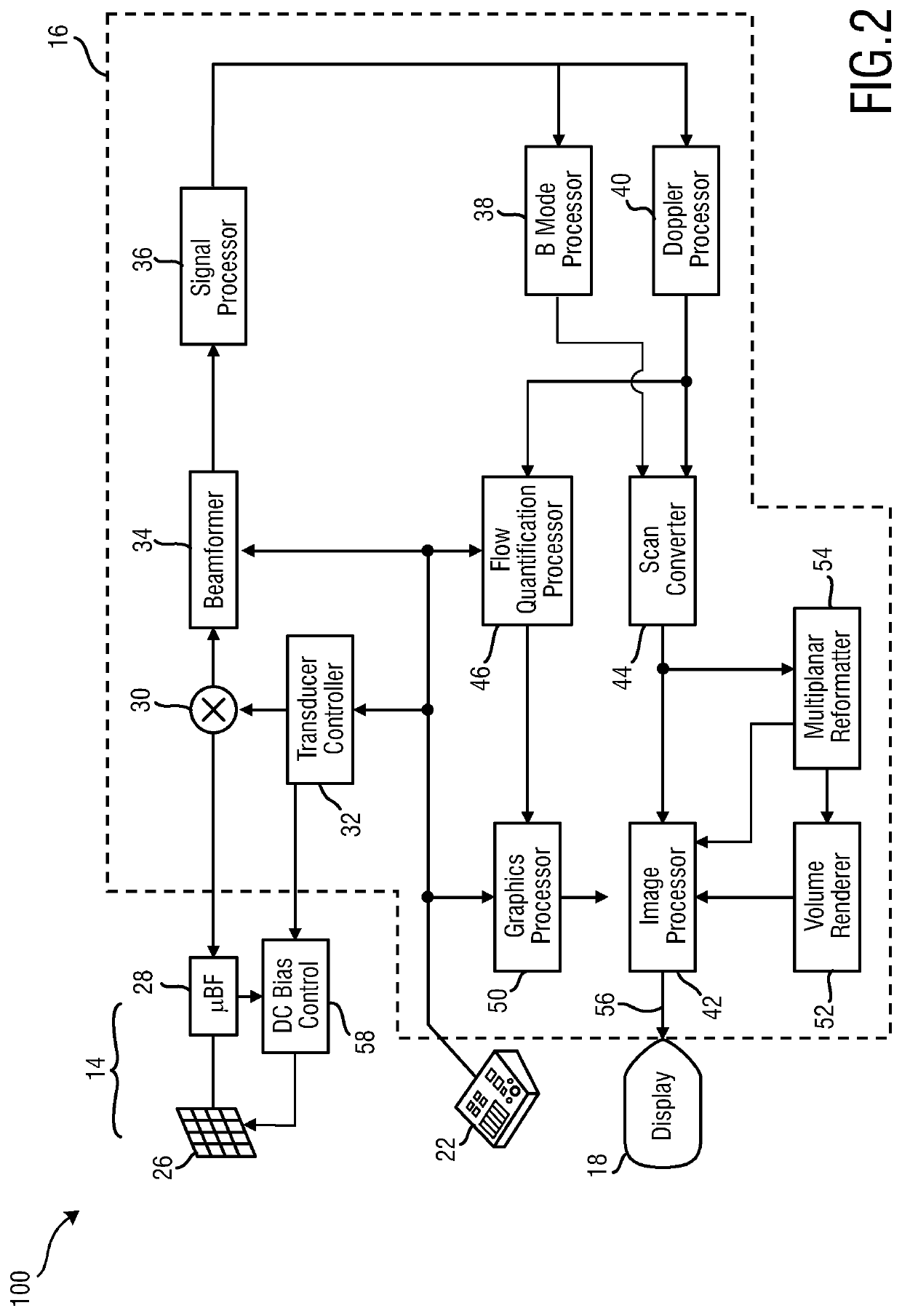
[0063]Before referring to the medical image processing device 10 according to the present invention, the basic principles of an ultrasound system 100 shall be explained with reference to FIGS. 1 and 2. Even though the field of ultrasound imaging is a preferred application of the herein presented medical image processing device 10, the presented medical image processing device 10 is not limited to the field of ultrasound imaging. The herein presented device 10 may also be used in other medical imaging modalities, such as, for example, CT, MR, MRI, etc.

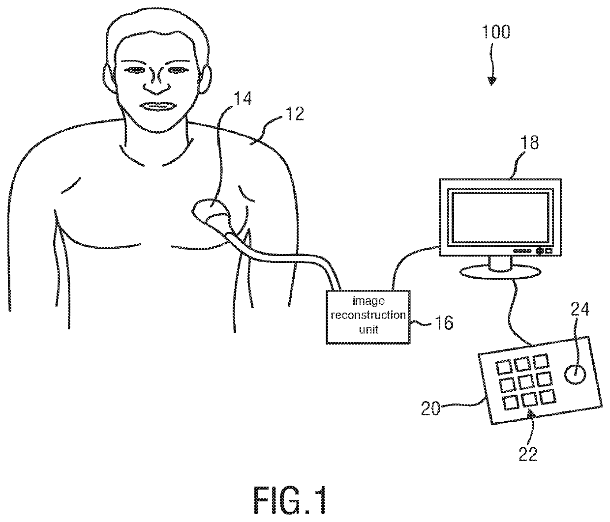
[0064]FIG. 1 shows a schematic illustration of an ultrasound system 100, in particular a medical three-dimensional (3D) ultrasound imaging system. The ultrasound imaging system 100 is applied to inspect a volume of an anatomical site, e.g. a heart of a patient 12. The ultrasound system 100 comprises an ultrasound probe 14 having at least one transducer array having a multitude of transducer elements for transmitting and / or receiving ult...


PUM


Abstract

The present invention relates to a medical image processing device (10), comprising: —a receiving unit (60) for receiving a first and a second medical image (72, 74) of an anatomical object of interest (84), wherein each of the first and the second medical images (72, 74) comprises a different field of view of the anatomical object of interest (84), and wherein the first medical image and the second medical image (72, 74) show a same or similar anatomical state of the anatomical object of interest (84); —a registration unit (64) that is configured to determine a transformation from an image space of the second medical image (74) to an image space of the first medical image (72); —a transformation unit (66) that is configured to transform the second medical image (74) into the image space of the first medical image (72) based on said transformation in order to receive a transformed second medical image (74′); and —a segmentation unit (68) that is configured to perform an overall segmentation that makes use of both the first medical image (72) and the transformed second medical image (74′) without fusing the first medical image (72) and the transformed second medical image (74′), wherein one and the same segmentation model (92) is simultaneously adapted to both the first medical image (72) and the transformed second medical image (74′) by identifying a first set of feature points (80) of the anatomical object of interest (84) within the first medical image (72), by identifying a second set of feature points (82) of the anatomical object of interest (84) within the transformed second medical image (74′), and by adapting the segmentation model (92) to both the first and the second set of feature points (80, 82).

Description

[0001]This application is the U.S. National Phase application under 35 U.S.C. § 371 of International Application No. PCT / EP2015 / 062752, filed on Jun. 9, 2015, which claims the benefit of European Application Serial No. 14172051.6, filed Jun. 12, 2014. These applications are hereby incorporated by reference herein.FIELD OF THE INVENTION[0002]The present invention generally relates to the field of medical imaging. In particular, the present invention relates to a medical image processing device for processing two- and / or three-dimensional medical images. The present invention further relates to a corresponding medical image processing method. Still further, the present invention relates to a computer program comprising program code means for causing a computer to carry out the steps of said method. An exemplary technical application of the present invention is the field of 3D ultrasound imaging. However, it shall be noted that the present invention may also be used in medical imaging ...

Claims


Application Information

Patent Timeline
Patent Type & Authority Patents(United States)
IPC IPC(8): A61B8/08G06T7/174G06T7/149G06T7/12G06T7/00
CPCA61B8/5246A61B8/0883G06T7/12G06T7/149G06T7/174G06T7/0012G06T2207/10136G06T2207/20061G06T2207/20112G06T2207/20124G06T2207/30048
Inventor BUERGER, CHRISTIANWAECHTER-STEHLE, IRINAWEBER, FRANK MICHAEL
Owner KONINKLJIJKE PHILIPS NV
Why Eureka
Try Eureka