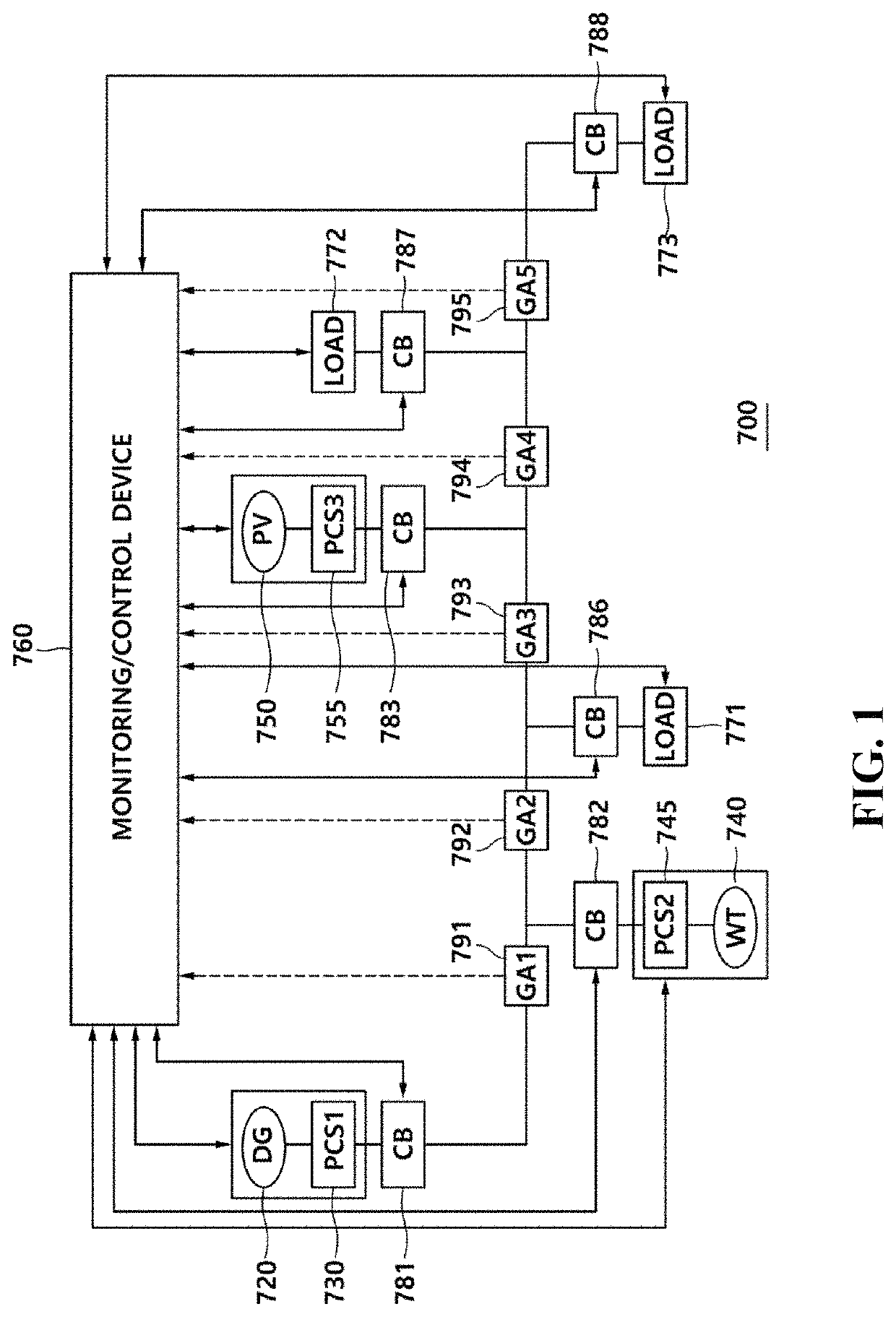
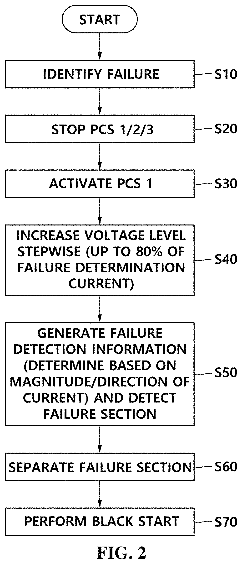
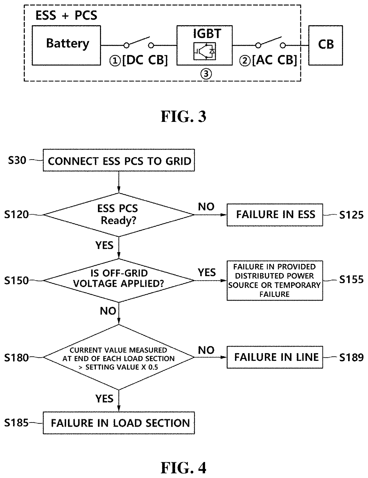
Microgrid system and method for managing malfunction

a micro-grid and malfunction technology, applied in the field of micro-grid systems, can solve the problems of frequent inconvenience of micro-grid systems installed in a remote area, affecting the entire micro-grid, and affecting so as to improve the reliability of the micro-grid system, and ensure the stability of grid operation.

Active Publication Date: 2021-05-04
HYOSUNG HEAVY IND CORP
View PDF12 Cites 4 Cited by
  • Summary
  • Abstract
  • Description
  • Claims
  • Application Information

AI Technical Summary

Benefits of technology

[0029]When a microgrid system or a failure management method according to the present invention having the above-described configuration is performed, there is an advantage of performing stable grid operation due to fast removal of a failure section and improving reliability of the microgrid system.
[0030]In addition, the microgrid system according to the present invention has an advantage in that it is not necessary to install a separate diesel generator or to provide a large capacity battery for each distributed power source for a failure test.
[0031]In addition, the microgrid system according to the present invention has an advantage of minimizing a power generation amount of a new renewable source discarded by a power failure.
[0032]In addition, the microgrid system according to the present invention has an advantage of being easily maintained and managed in a microsystem of a remote area such as islands constituting a stand-alone grid without connection to independent external power systems and being suitable for long current supply application.

Problems solved by technology

However, existing circuit breakers (MCCB, ACB, and the like) and failure management methods cannot adequately cope with various types of failures occurring in the microgrid, and thus, the entire microgrid can be affected by a localized failure, so that entire power failure may occur.
In particular, this leads to frequent inconvenience to the microgrid systems installed in a remote area such as islands having a stand-alone grid.
In the case of the related art, for the test power, each IED needs to have a relatively large capacity of energy storage device or a diesel generator for production of the test power, which inevitably causes an increase in equipment costs.

Method used


Image

  • Microgrid system and method for managing malfunction
  • Microgrid system and method for managing malfunction
  • Microgrid system and method for managing malfunction

Examples


Embodiment Construction

[0044]Hereinafter, embodiments of the present invention will be described with reference to the accompanying drawings.

[0045]In describing the invention, the terms first, second, and the like may be used to describe various components, but the components may not be limited by the terms. The terms are used only for the purpose of distinguishing one component from the others. For example, without departing from the scope of the present invention, a first component may be referred to as a second component, and similarly, a second component may also be referred to as a first component.

[0046]In a case where a component is referred to as being connected to or coupled with another component, the component may be directly connected to or coupled with another component, but it may be understood that still another component may exist between the components.

[0047]The terms used herein are used for the purpose of describing particular embodiments only and are not intended to limit the invention....


PUM


Abstract

Provided is a microgrid system having: a plurality of distributed power sources; a plurality of distributed loads; and lines for connecting the distributed power sources and the distributed loads, the microgrid system including: an ESS for storing power supplied from all or a portion of the distributed power sources and supplying the stored power to all or a portion of the distributed loads; an ESS PCS including an interruption means for converting the power stored in the ESS into AC power suitable for the microgrid and supplying the AC power to the microgrid in order to block connection to the microgrid in an abnormal state; and a monitoring / control device for gradually increasing a voltage output from the ESS PCS and performing processing for the failure when a failure is detected in the microgrid.

Description

TECHNICAL FIELD[0001]The present invention relates to a microgrid system for performing failure management and a failure management method using the same, and more particularly, to a system and a method capable of shortening a power failure time with respect to a non-failure section in which unnecessary power failure is experienced when a failure occurs in a grid.BACKGROUND ART[0002]A microgrid is a small-scale power source system configured with distributed power sources (solar power plant, wind power plant, and the like) and batteries (power storage devices) to supply power to loads. The microgrid is usually operated in a connected operation mode in which power is traded in connecting with a large scale power grid, and when a failure occurs in an electric-power-company-side line, the microgrid can be separated from the power grid to switch to a stand-alone operation mode. The microgrid is mainly installed in buildings, university campuses, factories, or the like and aims to reduce...

Claims


Application Information

Patent Timeline
Patent Type & Authority Patents(United States)
IPC IPC(8): H02J9/06H02H1/00H02H7/22H02J3/32H02J3/38H02J13/00H02J3/00
CPCH02J9/06H02H1/0007H02H7/22H02J3/32H02J3/382H02J13/0017H02J3/001H02H7/26G01R31/08H02J3/381H02J9/062H02J13/00004H02J2300/20H02J2300/40H02J2310/10H02J2300/10Y02P80/14Y04S10/123Y04S20/12Y04S20/248Y02E40/70Y02B70/30Y02B90/20Y04S40/121Y02E60/00H02J3/00125Y04S10/20Y04S10/14Y04S40/00H02J13/00007H02J3/38
Inventor JIN, DAE GEUNJIN, BO GUN
Owner HYOSUNG HEAVY IND CORP
Why Eureka
Try Eureka