

Valve stem structure and tire pressure monitoring system using the same
a valve stem and tire pressure monitoring technology, applied in the direction of tire measurement, vehicle components, transportation and packaging, etc., can solve the problems of increasing driver's expenses, inconvenience, extra expenditure, etc., and achieve the effect of saving unnecessary expenditures for consumers, improving user convenience, and reducing user's expenses
- Summary
- Abstract
- Description
- Claims
- Application Information
AI Technical Summary
Benefits of technology
Problems solved by technology
Method used
Image

Examples
first embodiment
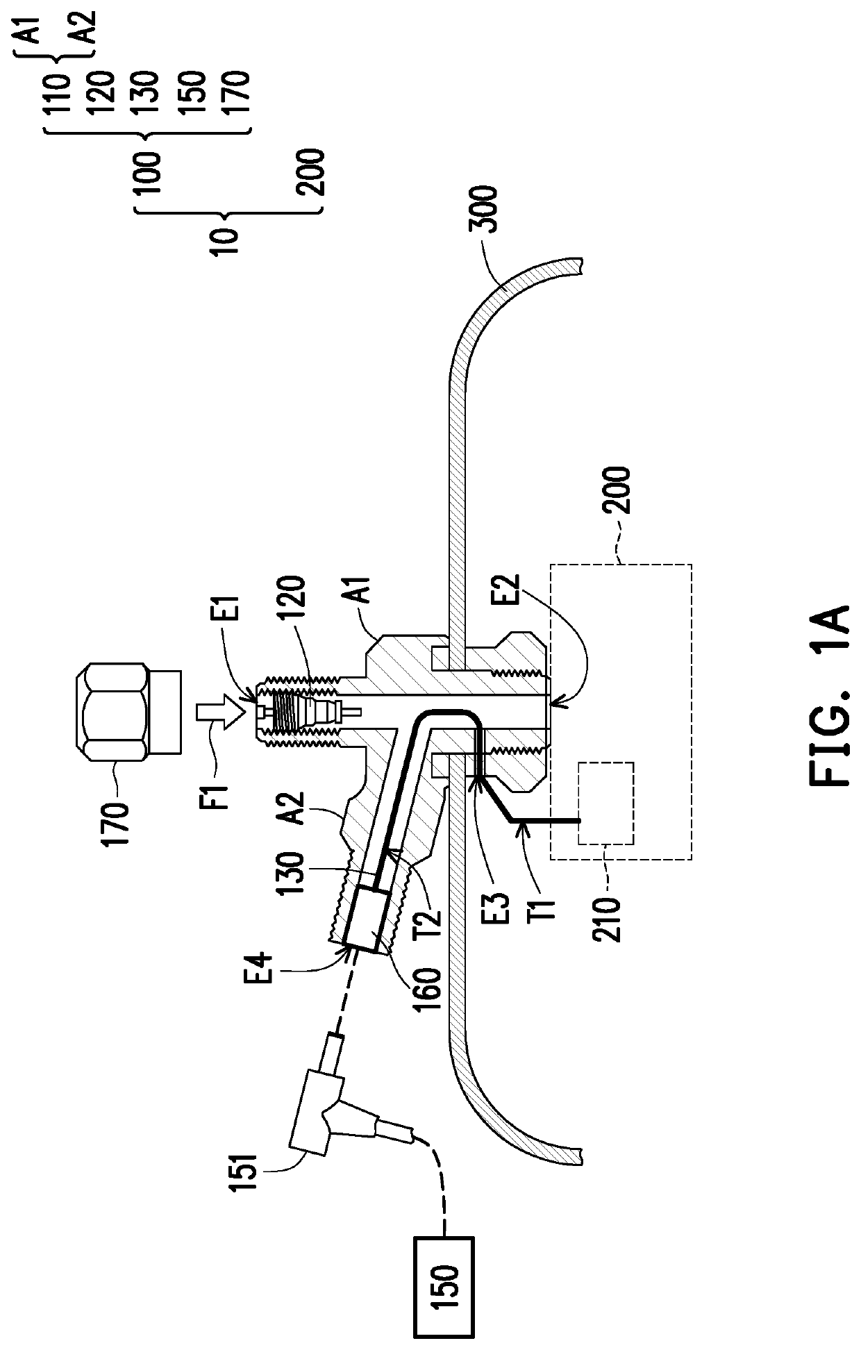
[0028]FIG. 1A is a schematic view showing a tire pressure monitoring system according to the disclosure. With reference to FIG. 1A, in this embodiment, a tire pressure monitoring system 10 includes a valve stem structure 100 and an electronic tire pressure monitoring device 200, wherein the electronic tire pressure monitoring device 200 is adapted to be disposed in a tire 300 and is fixed at a rim via the valve stem structure 100. The electronic tire pressure monitoring device 200 is a set of packaged electronic modules, and includes a pressure sensor, a radio frequency (RF) circuit board and a rechargeable battery cell 210 therein. The valve stem structure 100 is a self-contained valve device. When opened, the valve stem structure 100 allows a compressed air F1 to enter a tubeless tire or a space of an inner tube, and then automatically closes to seal the stored air to generate a pressure, thereby preventing the air from escaping out of the tire or the inner tube. Except for solid ...
second embodiment
[0033]FIG. 2 is a schematic view of a valve stem structure according to the disclosure, and this valve stem structure is applicable to the foregoing tire pressure monitoring system 10 as well. Different from the case of the previous embodiment, in a valve stem structure 400 here, a battery cell socket 420 is substantially disposed on a tube wall of a tube 410 and has a substantially uniform contour with an outer surface of the tube 410. An end T3 of a conducting wire 430, just like the first end T1 as described above, extends out of the tube 410 to be electrically connected to an electronic tire pressure monitoring device 200, and another end T4 of the conducting wire 430 is electrically connected to the battery cell socket 420. In this way, when a user joints an electrical connector (not shown) of a power source 150 to the battery cell socket 420 on the tube wall of the tube 410, an effect of power transmission may be achieved. Herein the battery cell socket 420 has magnetic proper...
third embodiment
[0035]FIG. 3 is a schematic view of a valve stem structure according to the disclosure, and this valve stem structure is applicable to the foregoing tire pressure monitoring system 10 as well. Different from the cases of the previous embodiments, in this embodiment, an air core 520 of a valve stem structure 500 is switched by a rod 521 to open and close a passage inside a tube 510, while the rod 521 is reset by an elastic component 522. A plating layer of an insulating material (as shown by the bold line in the drawing) is provided on the middle section of the rod 521 so that the rod 521 is insulated from the main body of the valve stem structure 500 (including other components of the valve stem structure 500 and other structure of the air core 520). An end portion of the rod 521 extends out of the air core 520 to be connected to a single-core conducting wire 530. Herein an end of the conducting wire 530 extends out of the tube 510 to be electrically connected to an anode of a batte...
PUM
 Abstract
Description
Claims
Application Information