Silver colored coated article with low-E coating having absorber layer and low visible transmission

Active Publication Date: 2021-06-08
GUARDIAN GLASS MANAGEMENT W L L
View PDF38 Cites 1 Cited by
  • Summary
  • Abstract
  • Description
  • Claims
  • Application Information

AI Technical Summary

Benefits of technology

[0012]Example embodiments of this invention relate to a coated article including a low-emissivity (low-E) coating. In certain example embodiments, the low-E coating is provided on a substrate (e.g., glass substrate) and includes at least first and second infrared (IR) reflecting layers (e.g., silver based layers) that are spaced apart by contact layers (e.g., NiCr based layers) and a dielectric layer of or including a material such as silicon nitride and an absorber layer of or including a material such as niobium zirconium which may be oxided (e.g., NbZrOx) and/or nitrided (e.g., NbZrOxNy). The addition of the absorber layer, which if oxided is preferably sub-oxided (partially oxided) and which if nitrided is preferably sub-nitrided (partially nitrided with fairly small amounts of nitrogen), has been found to increase durability and can be util

Problems solved by technology

It has been difficult to achieve desirable silver glass side reflective coloration in combination with acceptable solar values such as low sheet resistance, SF, and/or SHGC.
While low SF values are sometimes desirable for coated articles such as IG window units, the achievement of lower SF values may come at the expense of sacrificing coloration.
It is often desirable, but difficult, to achieve a combination of acceptable visible transmission, desirable glass side reflective coloration, and a low SF value for a coated article such as an IG window unit or the like.
However, these examples have undesirably high sheet resistance values of from 40-75 ohms/square, and undesirable green or bronze glass side reflective coloration.
Unfortunately, all Examples in US '899 suffer from undesir

Method used


Image

  • Silver colored coated article with low-E coating having absorber layer and low visible transmission
  • Silver colored coated article with low-E coating having absorber layer and low visible transmission

Examples


examples

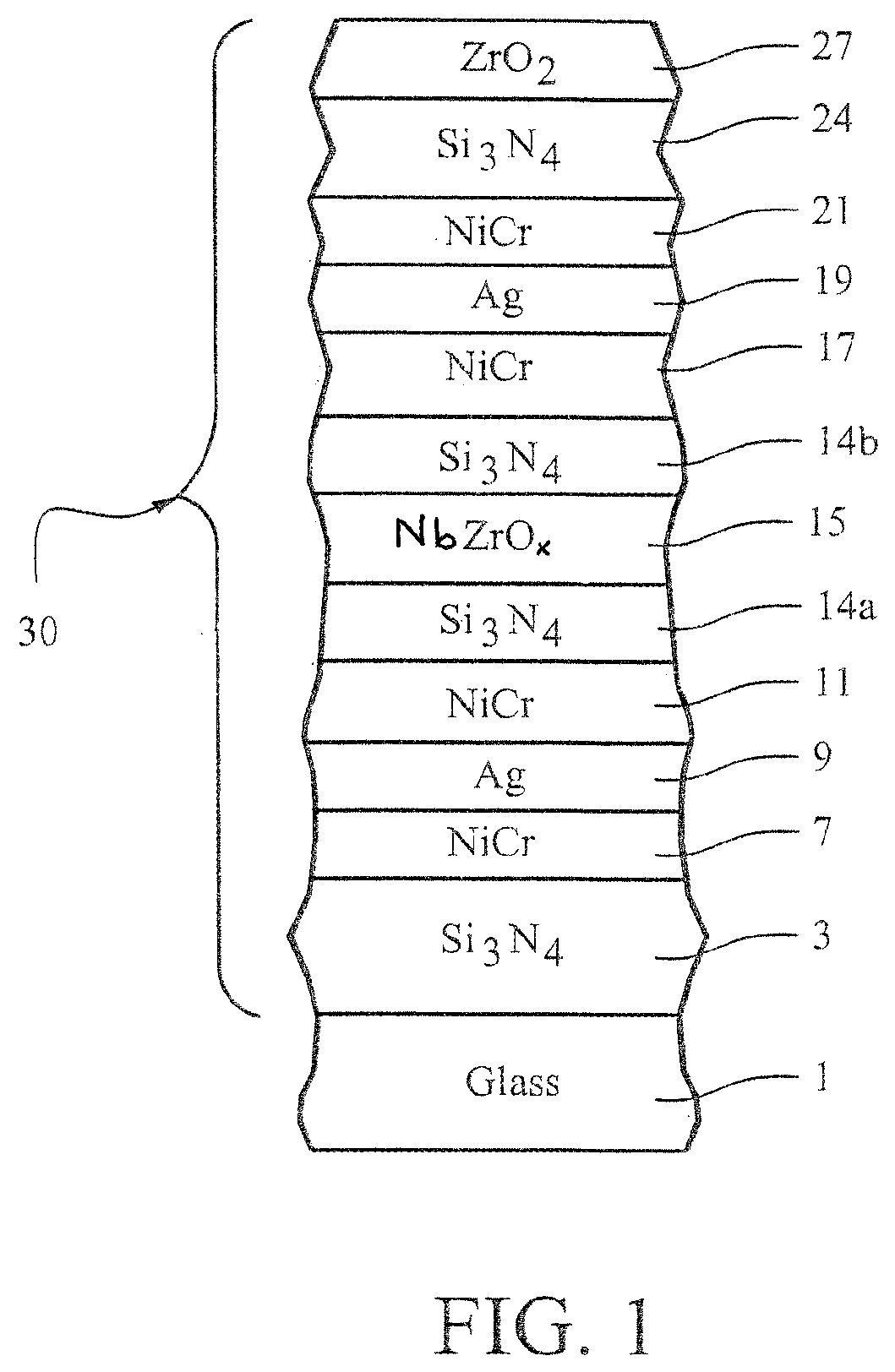
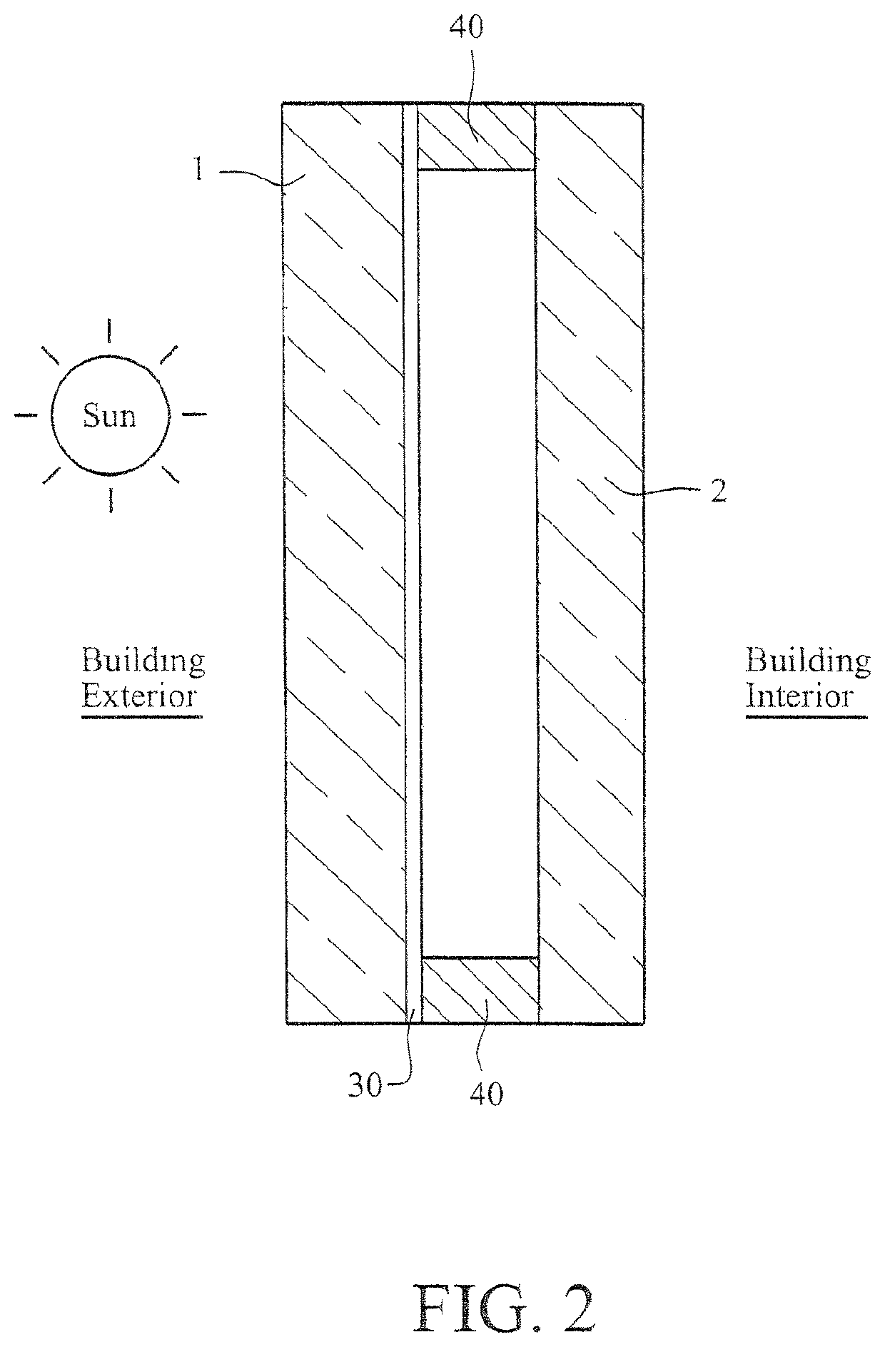
[0038]Examples 1 and 2 has the below-listed layer stack on a 5.9 mm thick, 75 mm×75 mm, clear matte glass substrate 1 as shown in FIG. 1. The examples were measured monolithically, heat treated and measured again after the HT. They were also put into IG window units after HT as shown in FIG. 2, and measured. The silicon nitride layers 3, 14, 24 in each example were deposited by sputtering a silicon target (doped with about 8% Al) in an atmosphere including argon and nitrogen gas. In the IG window unit, the matte glass substrates 1 and 2 were clear and 5.9 mm thick, and the air gap between the substrates in the IG window unit was 13 mm thick. The NbZr based absorber layer in each example was deposited by sputtering approximately 90 / 10 Nb / Zr magnetron sputtering targets in an atmosphere including argon and a small amount of nitrogen and oxygen gas (1.2 ml / kW of oxygen gas was used). Thus, the absorber layer 15 was of NbZrOxNy in these examples. Layer thicknesses for Examples 1-2 were ...


PUM

PropertyMeasurementUnit
Fractionaaaaaaaaaa
Fractionaaaaaaaaaa
Fractionaaaaaaaaaa

Abstract

A low-emissivity (low-E) coating on a substrate (e.g., glass substrate) includes at least first and second infrared (IR) reflecting layers (e.g., silver based layers) that are spaced apart by contact layers (e.g., NiCr based layers), a layer comprising silicon nitride, and an absorber layer of or including a material such as niobium zirconium which may be oxided and/or nitrided. The absorber layer is designed to allow the coated article to realize glass side reflective (equivalent to exterior reflective in an IG window unit when the coating is provided on surface #2 of an IG window unit) silver color. In certain example embodiments, the coated article (monolithic form and/or in IG window unit form) has a low visible transmission (e.g., from 15-45%, more preferably from 22-39%, and most preferably from 24-35%). In certain example embodiments, the coated article may be heat treated (e.g., thermally tempered and/or heat bent).

Description

[0001]This application is the U.S. national phase of International Application No. PCT / US2016 / 057439 filed Oct. 18, 2016, the entire content of which is hereby incorporated by reference in this application.[0002]This invention relates to a coated article including a low-emissivity (low-E) coating. In certain example embodiments, the low-E coating is provided on a substrate (e.g., glass substrate) and includes at least first and second infrared (IR) reflecting layers (e.g., silver based layers) that are spaced apart by contact layers (e.g., NiCr based layers), a layer comprising silicon nitride, and an absorber layer of or including a material such as niobium zirconium which may be oxided and / or nitrided. The absorber layer is designed to allow the coated article to realize glass side / exterior reflective silver color. In certain example embodiments, the coated article (monolithic form and / or in IG window unit form) has a low visible transmission (e.g., from 15-45%, more preferably fr...

Claims


Application Information

Patent Timeline
IPC IPC(8): B32B15/04B32B17/06B32B17/10C03C17/36
CPCB32B17/10229C03C17/366C03C17/3626C03C17/3636C03C17/3644C03C17/3649C03C17/3652C03C17/36C03C17/3639C03C17/3681C03C17/3642C03C23/007B32B17/06
Inventor BISWAS, ARITRABOYCE, BRENTCHU, ALLENLINGLE, PHILIP J.LORD, KENNETHNAIDU, MUNISWAMIVANTAKU, VENKATA KRISHNASWAMY NAIDU
Owner GUARDIAN GLASS MANAGEMENT W L L
Why Eureka
Try Eureka