Fuselage and aircraft including an air distribution multifunctional substructure and assembly method

a multi-functional, fuselage technology, applied in the direction of aircraft floors, space heating and ventilation details, domestic heating details, etc., can solve the problems of difficult maintenance or repair operations in the triangle zone, difficulty in fitting, and difficulty in assembling the fuselage of the aircraft, so as to facilitate maintenance and repair operations, simplify the time for assembling the fuselage, and free space

Active Publication Date: 2021-06-15
AIRBUS SAS
View PDF17 Cites 0 Cited by
  • Summary
  • Abstract
  • Description
  • Claims
  • Application Information

AI Technical Summary

Benefits of technology

[0012]Therefore, an aim of the present invention is to simplify and reduce the time for assembling an aircraft fuselage, and to optimize the arrangement thereof in order to gain free space volume mainly in the triangle zone and facilitate the maintenance and repair operations relating thereto.
[0013]Another aim of the invention is to reduce the number of references for pieces necessary for assembling a fuselage and to reduce the associated labor costs for the assembly thereof and possible repair and maintenance.
[0014]To this end, the invention proposes a fuselage fitted out in an optimized manner and including a multifunctional substructure making it possible to incorporate the ducts of an air distribution system with structural and / or functional components.
[0019]Indeed, it is possible to maintain equal performance for flow of the fluids (same pressure drop and same flow rate) when changing from a circular section to a slightly greater equivalent section of rectangular type. Thus, it is possible to substitute the circular section conventional pipe with the substantially rectangular section duct according to the invention and distribute air through the aircraft.
[0021]The assembly of the substantially rectangular section duct with other structural and / or functional components allows for obtaining the multifunctional substructure allowing the simultaneous assembly of the stiffeners, of the seat tracks and of pipes of the air distribution system. Moreover, the multifunctional substructure is arranged between the cross-members and the floor allowing access to the air distribution ducts from the passenger cabin, and the repair or maintenance thereof without needing to access the inside of the triangle zone.

Problems solved by technology

The reduced volume available, and the requirement for arranging so many elements poses several problems, particularly during the installation of these components (in the context of increasing production rates) and during the maintenance operations.
This piping with relatively large sections has an extremely light and fragile structure, which makes the fitting thereof particularly tricky and costly in terms of installation time.
Carrying out maintenance or repair operations in the triangle zone proves to be difficult due to the reduced space remaining available for a person to access and operate in this zone.
These operations therefore become long and costly, as well as tedious for the persons carrying them out.
Thus, acting upon particularly fragile and voluminous air-conditioning pipes is tricky and, moreover, this large piping makes the installation and the access of the other systems and the maintainability thereof in the triangle zone more difficult.
However, in these solutions, the only advantage obtained is the combination of the electrical functions with air piping without improving the problem of installing this piping which is all the more complex due to the problems of electrical connections.
If these solutions make it possible to reduce the number of components for installing a determined system in an aircraft, the installation and the arrangement of the components in the fuselage do not offer significant advantages with regard to the volume gains and the ease of the operations for installing and / or maintaining the components.

Method used


Image

  • Fuselage and aircraft including an air distribution multifunctional substructure and assembly method
  • Fuselage and aircraft including an air distribution multifunctional substructure and assembly method
  • Fuselage and aircraft including an air distribution multifunctional substructure and assembly method

Examples


Embodiment Construction

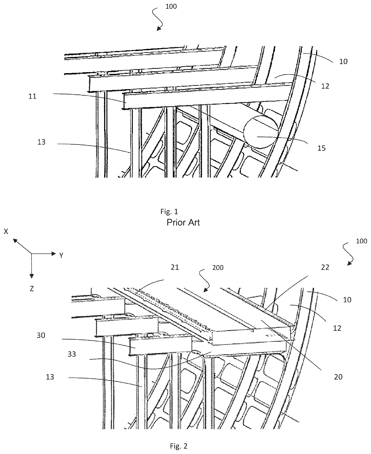
[0042]For the rest of the description, a longitudinal axis X is defined as the main axis of a fuselage, generally the longitudinal axis of an airplane in flight. Likewise, a transverse axis Y is defined perpendicular to the longitudinal axis, in practice parallel to the plane of the floor of the airplane cabin. Finally, a vertical axis Z completes the reference system.

[0043]FIG. 2 shows an isometric view of a fuselage section part according to the invention wherein only the main elements of the structures are shown in a simplified form for clarity of the illustration. The figure depicts a fuselage 100 comprising frames 10, a fuselage skin 12, strengthening rods 13 supporting cross-members 30 and bearing on a lower part of the frame of the fuselage (zone not visible in the drawing).

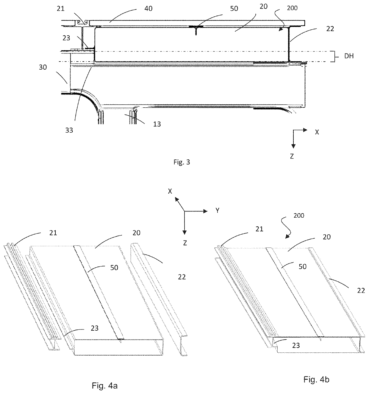
[0044]The fuselage 100 includes a multifunctional substructure 200 incorporating a duct 20 of an air distribution system of rectangular section. The duct 20 includes, on an internal lateral wall, a track 2...


PUM


Abstract

An aircraft fuselage including a fuselage skin, cross-members supporting a floor of the aircraft, wherein the fuselage includes a multifunctional substructure fixed to at least one of the cross-members in a lowered part of the cross-member. The multifunctional substructure comprises: at least one duct of an air distribution system having a substantially rectangular section at the location of the at least one cross-member and having lateral walls of the duct that are substantially vertical; a seat fixing track or a stiffener fixed on a first lateral wall of the duct of the multifunctional substructure, and; a seat fixing track or a stiffener fixed on a second lateral wall, opposite the first lateral wall, of the duct of the multifunctional substructure.

Description

CROSS-REFERENCES TO RELATED APPLICATIONS[0001]This application claims the benefit of the French patent application No. 1756554 filed on Jul. 11, 2017, the entire disclosures of which are incorporated herein by way of reference.BACKGROUND OF THE INVENTION[0002]The present invention pertains to the field of engineering of aircraft fuselage structures. In particular, the invention relates to a fuselage and an aircraft including a multifunctional substructure comprising a duct of an air distribution system combined with cabin floor support structures of the fuselage and / or with seat fixing tracks.[0003]In aircraft, in particular in airplanes, the structure of a passenger floor is supported by link rods placed between the cross-members and the frames of the fuselage. These link rods define a substantially triangular section zone which is formed between the passenger floor, the frame of the fuselage and the floor rods. The volume of space available in this so-called “triangle” zone is qui...

Claims


Application Information

Patent Timeline
Patent Type & Authority Patents(United States)
IPC IPC(8): B64D13/00F24F13/02B64D13/06B64C1/06B64C1/12B64C1/20B64C1/00B64C1/18B64D11/00
CPCB64D13/06B64C1/00B64C1/061B64C1/068B64C1/12B64C1/18B64C1/20B64D13/00F24F13/0227B64C2001/0072B64C2001/0081B64D2011/0046B64D2221/00F24F13/0245F24F13/0254F24F2221/40B64D11/0696B64F5/10E04B5/10
Inventor BERMUDEZ, MICHELTHOMAS, BRUNOGUIMARD, JEAN-MATHIEU
Owner AIRBUS SAS
Why Eureka
Try Eureka