
Catheter device, comprising a valve for controlling a fluid flow through a catheter

a catheter and valve technology, applied in the field of mechanical devices, can solve the problems of a very restricted application area of off valves

Active Publication Date: 2021-06-29
ECP ENTWICKLUNGSGMBH
View PDF17 Cites 0 Cited by
  • Summary
  • Abstract
  • Description
  • Claims
  • Application Information

AI Technical Summary

Benefits of technology

The invention is a catheter device that can precisely guide rinsing fluid in and out of the device. This is especially useful when using flexible rotating shafts that may have changing pressure conditions. The valves in the device are designed to function perfectly, and can be easily cleaned and replaced. The device also allows for quick and reliable access to different closure positions with minimal movement of the closure element. These technical improvements make the device more efficient, reliable, and cost-effective.

Problems solved by technology

Such shut-off valves basically have a very restricted area of application, wherein problems either occur at overpressure or underpressure or in the case of pressure fluctuations, since such valves are often only designed for a narrow pressure range.

Method used


Image

  • Catheter device, comprising a valve for controlling a fluid flow through a catheter
  • Catheter device, comprising a valve for controlling a fluid flow through a catheter
  • Catheter device, comprising a valve for controlling a fluid flow through a catheter

Examples


Embodiment Construction

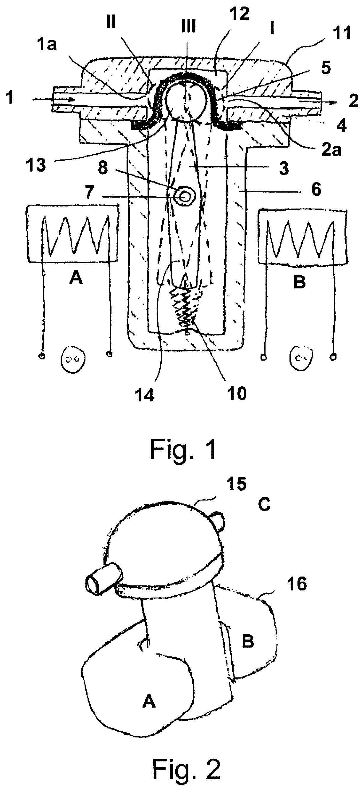
[0063]FIG. 1 schematically shows a valve body 11 with a feed channel 1, a discharge channel 2 as well as a drive lever 3 which deflects a membrane 5. The membrane 5 closes the valve control space 12 which is located within the valve body 11, in a fluid-tight manner, and can be pressed by a spherical end 13, selectively against the feed opening 1a or the discharge opening 2a, in order to either close the feed channel 1 or the discharge channel 2.

[0064]The drive lever 3 is pivotable about a shaft 7, which with spacer sleeves 8 is mounted in the drive housing 6. The drive lever 3 is represented once in an unbroken manner in the third position III, in which it leaves open a connection channel between the feed opening 1a and the discharge opening 2a, as well in a dashed manner in a first position I, in which the spherical end 13 closes the discharge opening 2a by way of the membrane 5, and also dashed, in a second position II, in which the drive lever closes the feed opening 1a by way of...


PUM


Abstract

The invention relates to a catheter device (100) comprising a catheter (68) for insertion into a living being and at least one lumen (69, 70, 74, 79) for guiding a fluid flow within a section of the catheter device, and comprising a valve for controlling a fluid flow, in particular through a catheter, having a valve control chamber (12, 12a), into which an inlet opening (1a) of an inlet channel (1) and an outlet opening (2a) of an outlet channel (2) open, and further having a closure element (5, 13, 17) which can be moved in the valve control chamber (12, 12a) in a controlled manner and which, in at least a first position (I), closes the outlet opening (2a), in at least a second position (II) closes the inlet opening (1a), and which, in at least a third position (III), keeps open a connecting channel between the inlet opening (1a) and the outlet opening (2a), a valve train (A, A′, B, B′, 3, 14, 18) being provided and optionally moving the closure element (5, 13, 17) to at least the first, second or third position, and the at least one lumen (68, 70, 74, 79) being fluidically connected to the inlet channel or the outlet channel.

Description

CROSS-REFERENCE TO RELATED APPLICATION[0001]This application is a continuation of U.S. application Ser. No. 15 / 545,003, filed on Jul. 20, 2017, which is a national stage filing under 35 U.S.C. § 371 of International Application No. PCT / EP2016 / 051358, filed on Jan. 22, 2016, which claims priority to European Patent Application No. EP15152201.8, filed on Jan. 22, 2015. The specifications of each of the foregoing applications are hereby incorporated by reference in their entirety.FIELD OF THE INVENTION[0002]The invention lies in the field of mechanics and is particularly advantageously applicable to the field of medical technology. It relates in particular to a valve which even at different pressure conditions permits a reliable blocking of a fluid flow through a catheter.BACKGROUND[0003]Various shut-off valves for the control of fluid flows are known from the state of the art. An industrially developed disposable shut-off valve is disclosed for example in DE 20 2013 104711 A1. A simpl...

Claims


Application Information

Patent Timeline
Patent Type & Authority Patents(United States)
IPC IPC(8): A61M60/892A61M39/22A61M60/135A61M60/148A61M60/279A61M60/829A61M25/00A61M60/205A61M60/414A61M60/13A61M60/438A61M60/523A61M60/546
CPCA61M60/892A61M25/0043A61M39/22A61M39/223A61M60/135A61M60/148A61M60/279A61M60/829A61M60/205A61M60/414A61M2039/224A61M2039/226A61M2205/0272A61M2205/7545A61M60/82A61M60/216A61M60/13B03C1/14A61M60/546A61M60/523A61M60/438A61M25/003A61M25/10185
Inventor LIEBING, REINER
Owner ECP ENTWICKLUNGSGMBH
Learn More