Reducing agent supply system for cement plant low-temperature SCR denitration and control method

A supply system and reducing agent technology, applied in the field of flue gas denitrification, to achieve good service environment, small reduction in flue gas temperature, and reduced energy consumption of heat sources

Pending Publication Date: 2022-06-28
天津中材工程研究中心有限公司 +1
View PDF0 Cites 0 Cited by
  • Summary
  • Abstract
  • Description
  • Claims
  • Application Information

AI Technical Summary

Problems solved by technology

[0009] The purpose of this application is to provide a kind of ammonia water with a mass fraction between 15% and 25% in order to solve the technical problems caused by using ammonia water with a mass fraction between 15% and 25% as

Method used


Image

  • Reducing agent supply system for cement plant low-temperature SCR denitration and control method
  • Reducing agent supply system for cement plant low-temperature SCR denitration and control method
  • Reducing agent supply system for cement plant low-temperature SCR denitration and control method

Examples


Example Embodiment

[0041] Example 1

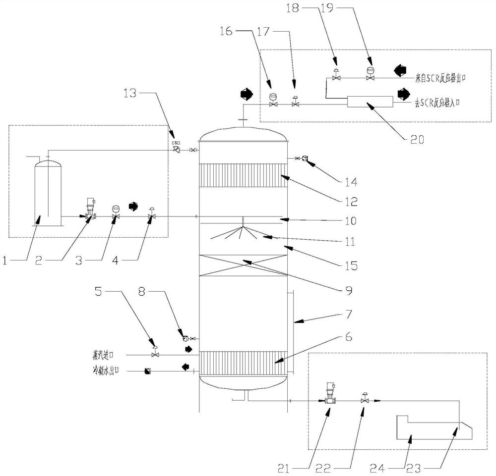
[0042] This embodiment includes an ammonia water storage and delivery module, an ammonia water low-temperature evaporation-self-cooling separation module, an ammonia gas dilution and temperature rise module, a waste water treatment module, and a control module.

[0043] The ammonia water storage and delivery module includes an ammonia water storage tank 1, an ammonia water delivery pump 2, an ammonia water flow meter A3 and an ammonia water flow regulating valve A4.

[0044] The top of the ammonia water storage tank 1 is provided with an ammonia water unloading port and an ammonia gas receiving port with a long pipe to receive the ammonia gas delivered by the ammonia gas safety valve 13. The long pipe is required to go deep into the bottom of the ammonia water storage tank and be lower than the ammonia water level. , The upper part of the ammonia water storage tank is provided with a thermometer and a pressure gauge, the side of the tank is provided with a l...

Example Embodiment

[0053] Example 2

[0054] This embodiment includes the following steps:

[0055] S1, the ammonia water with a mass concentration of 15%-25% uses the ammonia water tanker's own pump to enter the ammonia water storage tank 1 through the ammonia water unloading port at the top of the ammonia water storage tank; according to the denitration requirement, the ammonia water in the ammonia water storage tank 1 passes through the ammonia water delivery pump. 2 and the ammonia water flow regulating valve A4 to adjust and control the flow, and the ammonia water whose flow meets the requirements is sent to the middle of the gas-liquid separator 15 .

[0056] S2. The ammonia water sent to the gas-liquid separator 15 is sprayed into the gas-liquid separator 15 through the multi-layer self-cooling coil 10 and the liquid distribution nozzle 11 in the middle. The sprayed ammonia water droplets conduct heat exchange with the ammonia gas evaporated from the bottom of the gas-liquid separator 15...


PUM


Abstract

The invention belongs to the technical field of flue gas denitration, and particularly relates to a reducing agent supply system for low-temperature SCR denitration of a cement plant and a control method.The ammonia water low-temperature evaporation-self-cooling separation module comprises a gas-liquid separator, a heater is arranged at the bottom of the gas-liquid separator and connected with a steam pipeline, and the steam pipeline is connected with the ammonia water low-temperature evaporation-self-cooling separation module; a steam flow regulating valve is arranged on the steam pipeline, a heat exchange packing layer is arranged in the middle of the gas-liquid separator, a self-cooling coil connected with the ammonia water pipeline is arranged above the heat exchange packing layer, and a demister is arranged at the top of the gas-liquid separator. The invention provides a reducing agent supply system for cement plant low-temperature SCR denitration and a control method. According to the reducing agent supply system and the control method, ammonia water with the mass fraction ranging from 15% to 25% forms high-purity ammonia gas in a low-temperature evaporation-self-cooling mode.

Description

technical field [0001] The invention belongs to the technical field of flue gas denitration, and in particular relates to a reducing agent supply system and a control method for low-temperature SCR denitration in a cement plant. Background technique [0002] current technology: [0003] In recent years, my country's environmental protection standards have become increasingly strict. In the field of flue gas denitrification, SCR denitration technology has high denitrification efficiency, reducing agent (NH 3 ) has the advantages of high utilization rate and has been widely used. The traditional medium and high temperature SCR denitration technology is suitable for the flue gas temperature above 200 ℃. The reducing agent is generally supplied by liquid ammonia gasification, urea decomposition or directly sprayed into the flue gas with a mass fraction of 15%-25% by using an atomizing spray gun. of ammonia. Among the above three reducing agent supply methods: liquid ammonia i...

Claims


Application Information

Patent Timeline
IPC IPC(8): B01D53/90B01D53/86B01D53/56
CPCB01D53/90B01D53/8696B01D53/8631B01D2251/2062B01D2258/0283
Inventor 王永刚程兆环黄庆唐新宇张涛杜亮波崔小璇
Owner 天津中材工程研究中心有限公司
Why Eureka
Try Eureka