Measurement device and measurement method for measuring temperature and emissivity of a measured surface

a measurement device and measurement method technology, applied in the field of measurement, can solve the problems of sharp decline in the effective emissivity, the inability to reach 1, and the inability to measure the surface temperature accurately, and achieve the effect of more accurately measuring the temperature and emissivity of the measured surfa

Active Publication Date: 2021-06-29
SHENYANG TAIHE METALLURGY MEASUREMENT & CONTROL TECH
View PDF18 Cites 0 Cited by
  • Summary
  • Abstract
  • Description
  • Claims
  • Application Information

AI Technical Summary

Benefits of technology

[0009]The object of the present application is to provide a measurement device and a measurement method capable of more accurately measuring a temperature and an emissivity of a measured surface.
[0018]First, the measurement accuracy is improved, and the reasons lie in that: 1) in order to obtain two states of receiving radiation, there is no need to move the reflector, and the gap between the reflector and the measured surface may be smaller or there is even no gap (the reflector may be in contact with the measured surface), so that the radiation light emitted from the measured surface and escaping via a gap at the bottom is reduced or eliminated, and the measurement accuracy is raised; 2) it is only necessary to move the absorber tube so as to effectuate shifting between two states of receiving radiation, and compared to movement of a reflector, the absorber tube has a smaller volume and a lighter mass and moves at a shorter distance (for example, if it is a hemispherical reflector, it is necessary to move a distance equal to radius of the reflector), so as to realize a faster shifting speed, a less damage of a surface temperature field, and a more accurate measurement; 3) it is not necessary to move the reflector, so as to help eliminate an interference by the background radiation, and also improve the measurement accuracy: 4) it may not only measure a normal emissivity, and may design the position of the absorber tube relative to the reflector, so as to measure a non-normal emissivity.
[0019]Second, from the aspect of application, since there is no need for auxiliary structures such as a guide rail and a support frame, and there is no need to move the reflector, it has the advantages of smaller space and less requirements needed for measurement, a lower cost, a favorable portability without an interference by the background radiation: and it is adapted to an occasion with limited space, or an occasion requiring rapid measurement, or an occasion in which a guide rail and a support frame cannot be installed, for example a steel blank surface and a continuously cast blank surface within a heating furnace of a steel plant with a significant background radiation.

Problems solved by technology

When a radiation thermometer is utilized to measure a surface temperature, measurement accuracy of the surface temperature has always been an unsolved problem in the field of metrological test under influence of emissivity.
However, there is virtually no ideal reflector, a reflector has a reflectance of less than 1, and an optical radiation aperture in the reflector and a gap to the measured surface lead to a non-hermetic cavity, so that effective emissivity cannot reach 1.
First, from the aspect of accuracy: 1) the reflector in the aforementioned two patent documents is required be installed on a guide rail so as to realize movement on a measured surface, and there is necessarily a gap to the measured surface so that the radiation light emitted from the measured surface may escape from the gap, so as to affect the measurement accuracy. At the same time, it can be known by theoretical calculation that, the hemispherical reflector is particularly sensitive to the distance to the measured surface, if the spherical center deviates from the measured surface, it may cause a sharp decline in the effective emissivity, so that the bottom gap remarkably affect the measurement accuracy.
2) The reflector has a damaging effect on the temperature field of the measured surface, so the reflector cannot perform long-time measurement (Gao Kuiming et al., Research on a temperature thermometer with an anterior reflector, 1984, FIG. 5). If the reflector measures stainless steel of 700° C., the measured surface temperature rises about 4° C. when the reflector covers for 1 second and rises about 6° C. for 2 seconds. Thus, rapid measurement is required. Moreover, in the aforementioned patent documents it is at least necessary to move at a distance equal to twice the radius of the reflector in order to shift the reflector between two states of receiving radiation. In shifting process, a temperature field is inevitably damaged, thereby affecting the measurement accuracy.
3) When the reflector is moved away in the aforementioned two patent documents, the measured surface is exposed in the space and the surrounding background radiation may be reflected by the measured surface to the optical aiming probe. Thus, the measurement signal which may be subject to an interference by the background radiation, can only be applied in an ideal laboratory surrounded with cold walls, but cannot be applied in industrial fields.
4) The aforementioned two patents only measure the normal emissivity, but cannot measure the directional emissivity.
Second, from the aspect of application, before measuring using the measurement devices disclosed in the aforementioned two patent documents, a guide rail and a support frame have to be installed, and the guide rail have to be adjusted to be horizontal to the measured surface. When the reflectors have the same dimension, a space at least covering the reflector is needed for its movement. With much space and high requirement needed for installation, a high cost and a poor portability, and a significant influence by the background radiation, it is not suitable for industrial fields with strong background radiation, such as an occasion with limited space, or an occasion requiring rapid and convenient measurement, or an occasion in which a guide rail and a support frame cannot be installed, for example a steel blank surface and a continuously cast blank surface within a heating furnace of a steel plant with a significant background radiation.

Method used


Image

  • Measurement device and measurement method for measuring temperature and emissivity of a measured surface
  • Measurement device and measurement method for measuring temperature and emissivity of a measured surface
  • Measurement device and measurement method for measuring temperature and emissivity of a measured surface

Examples


first embodiment

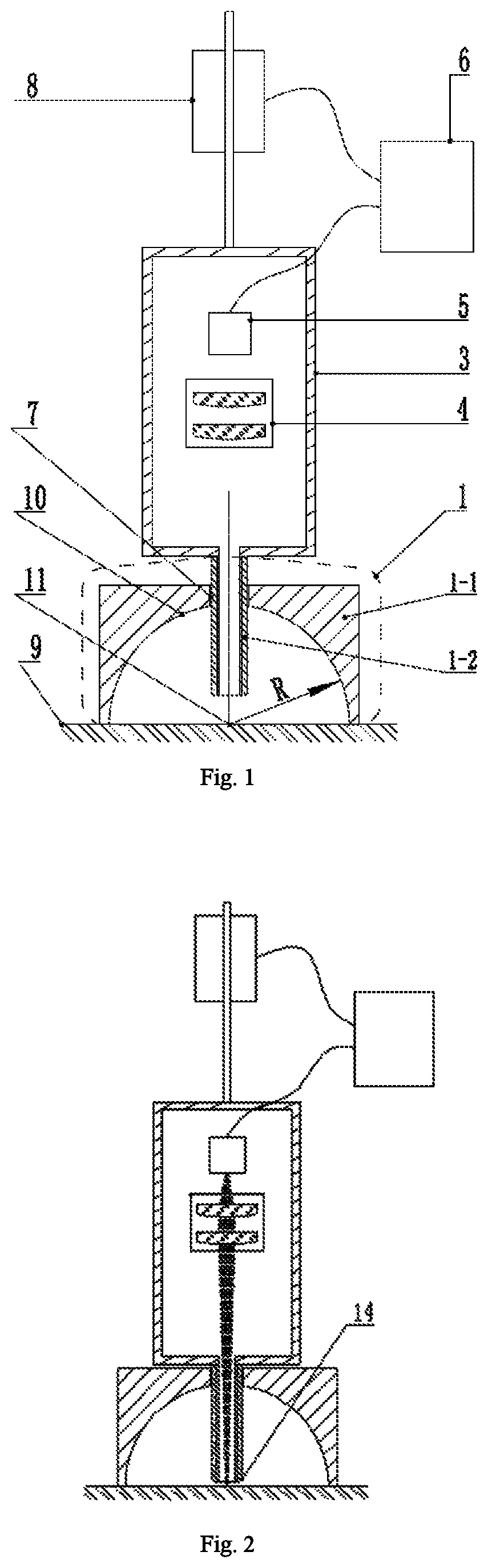
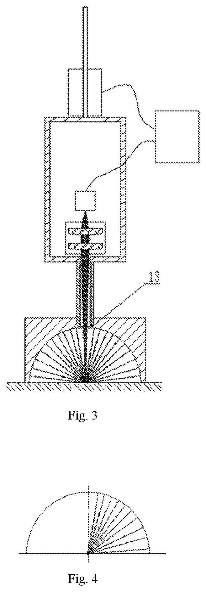
[0078]FIGS. 1 to 3 show the structure and operational principles of the measurement device according to the first embodiment of the present application.

[0079]As shown in FIGS. 1 to 3, the measurement device of the first embodiment comprises a reflection converter 1, a driving device 3, an optical receiver 5, a data processor 6, and a displayer as a measurement result output device.

[0080]The reflection converter 1 comprises a reflector 1-1, an absorber tube 1-2, and a light guide structure 4. In the present embodiment, the light guide structure 4 is a lens assembly.

[0081]The reflector has a through hole 7, and the reflection surface 10 of the reflector 1-1 is a hemispherical surface. Wherein, the reflection surface 10 of the reflector 1-1 is a hemispherical surface. The bottom surface of the reflector 1-1 is planar, and the bottom circle of the hemispherical surface is located on the bottom surface.

[0082]In the present embodiment, the ratio of the diameter of the through hole 7 of th...

second embodiment

[0102]The second embodiment is a measurement method for measuring the temperature and the emissivity of the measured surface 9 using the measurement device of the first embodiment.

[0103]In the present embodiment, the specific measurement steps of the measurement method are as follows:

[0104]The step of obtaining expressions of radiation brightness at the first measurement position: the reflector 1-1 of the measurement device is positioned on the measured surface 9; the driving mechanism 3 drives the absorber tube 1-2 to move to the first measurement position and hold. The reflector 1-1 of the measurement device is placed on the measured surface 9 to allow that the reflector 1-1 and the measured surface 9 are in contact and maintained, thus, at this time, the reflection action of the reflector 1-1 is disenabled, and part of the radiation energy emitted from the spherical center 11 is absorbed by the inner surface of the absorber tube 1-2, and the other part is projected onto the photo...

third embodiment

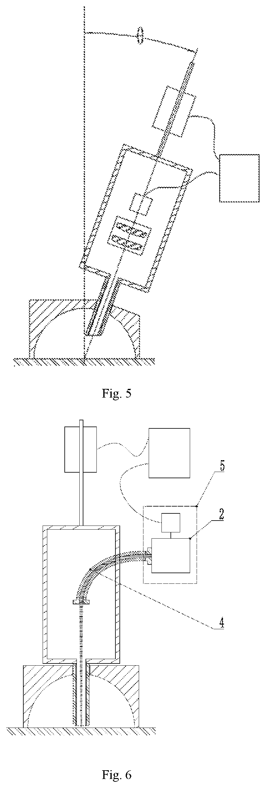
[0122]As shown in FIG. 5, the difference between the present embodiment and the first embodiment lies in that the axis of the absorber tube 1-2 forms an angle θ with the diameter perpendicular to the bottom surface of the reflector 1-1, so that during the measurement, after the bottom surface is placed on the measured surface 9, the axis of the absorber tube 1-2 forms an angle θ with the normal of the measured surface 9. The present embodiment may measure the emissivity in the direction of the angle θ. In the present embodiment, the angle θ is 30°.

[0123]For other unspecified parts in the third embodiment, reference may be made to the related content in other respective embodiments.


PUM

PropertyMeasurementUnit
angleaaaaaaaaaa
emissivityaaaaaaaaaa
surface temperatureaaaaaaaaaa

Abstract

measurement device and a measurement method for measuring a temperature and an emissivity of a measured surface are provided. The measurement device includes a reflection converter, an optical receiver and a data processor. The reflection converter includes a reflector having a through hole and an absorber tube shifted between a first measurement position and a second measurement position relative to the reflector. In the first measurement position, the light incident end of the absorber tube approaches or contacts the measured surface, such that the optical receiver forms a first electrical signal. In the second measurement position, the light incident end of the absorber tube is located at or outside the through hole, such that the optical receiver forms a second electrical signal. The data processor is configured to determine a temperature and an emissivity of the measured surface according to the first electrical signal and the second electrical signal.

Description

FIELD[0001]The present application relates to the technical field of measurement, and in particular relates to measurement device and measurement method for measuring temperature and emissivity of a measured surface.BACKGROUND[0002]When a radiation thermometer is utilized to measure a surface temperature, measurement accuracy of the surface temperature has always been an unsolved problem in the field of metrological test under influence of emissivity. Various types of radiation thermometers widely used in the prior art are calibrated under the condition of a standard metrological instrument of laboratory—blackbody radiation source (its emissivity≈1). During the measurement, the measured temperature T may be obtained according to a radiation signal and a calibration equation. However, emissivity of an actual object is less than 1, and during the measurement, there is obtained only a brightness temperature rather than an actual surface temperature. The emissivity of an actual object w...

Claims


Application Information

Patent Timeline
Patent Type & Authority Patents(United States)
IPC IPC(8): G01J5/08G01J5/00G01J5/52G01N21/55
CPCG01J5/0815G01J5/00G01J5/0022G01J5/0809G01J5/522G01N21/55G01J5/0887G01J5/0818G01J2005/0074G01J5/084G01J5/60G01J5/085G01J5/53G01J5/0808
Inventor XIE, ZHICHE, XUNJIANXIE, QIXIANWANG, LIZHONG
Owner SHENYANG TAIHE METALLURGY MEASUREMENT & CONTROL TECH
Why Eureka
Try Eureka