Low-power DC-DC converter capable of preventing reverse current with digital operations and method of operating the same

a low-power dc-dc converter and digital operation technology, applied in the direction of electric variable regulation, process and machine control, instruments, etc., can solve the problems of reducing the feature size of a process to a sub-micron level, affecting the operation method of the corresponding digital operation method, and affecting the operation of the battery. to prevent the effect of reverse curren

Active Publication Date: 2021-08-17
ABOV SEMICON
View PDF21 Cites 2 Cited by
  • Summary
  • Abstract
  • Description
  • Claims
  • Application Information

AI Technical Summary

Benefits of technology

[0014]An object of the present invention is to provide a DC-DC converter capable of preventing reverse current with digital operations in a low power supply circuit and a method of operating the DC-DC converter.
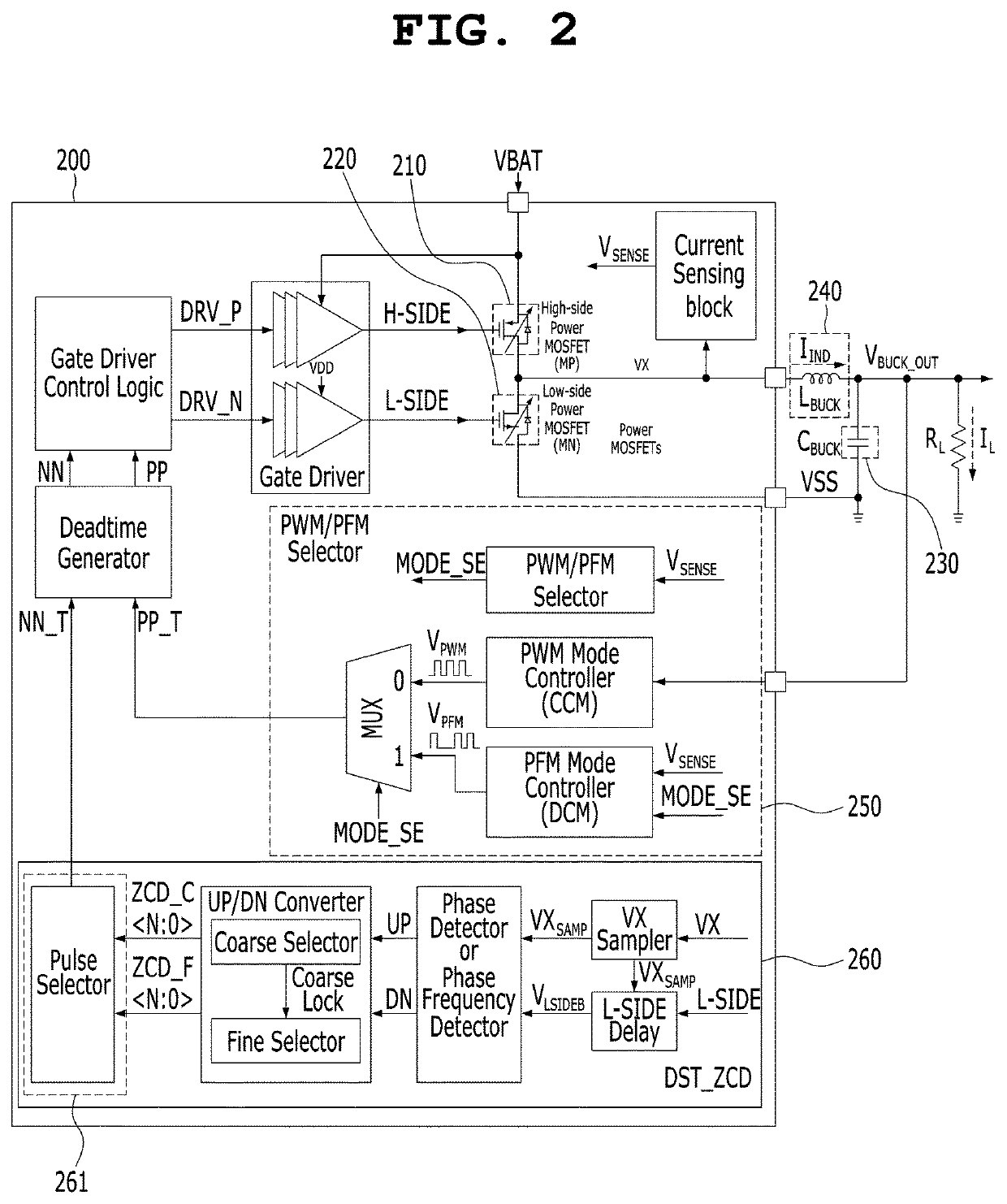
[0016]An object of the present invention is to propose a detection method of, when detecting a reverse current blocking point with digital operations, transferring detected information to a subsequent stage without loss, thereby improving the accuracy of a reverse current blocking point.
[0017]An object of the present invention is to propose a detection method in which a VX sample signal obtained by sampling the voltage of a VX node, which is a common contact point, is not dependent upon a specific reference signal and information about the operation of the voltage of the VX node in time domain is included, thereby improving the accuracy of a reverse current blocking point.
[0018]An object of the present invention is to effectively reduce the time required to reach an equilibrium point at which the error of a reverse current blocking point is minimized.
[0020]An object of the present invention is to reduce the number of switching cycles required to reach an optimized reverse current blocking point in such a manner that the sampling interval of a VX node and a pulse width adjustment, which is a unit for the adjustment of a pulse width, are separated to be independent of each other, so that time resolution can be increased by reducing the sampling interval and the pulse width can be adjusted variably.

Problems solved by technology

Recently, with the development of mobile devices, the run time of a battery has become a significant issue.
In order to optimize low-power operation and achieve high efficiency, the feature size of a process is being reduced to a sub-micron level, and a corresponding digital operation method is becoming a significant issue.
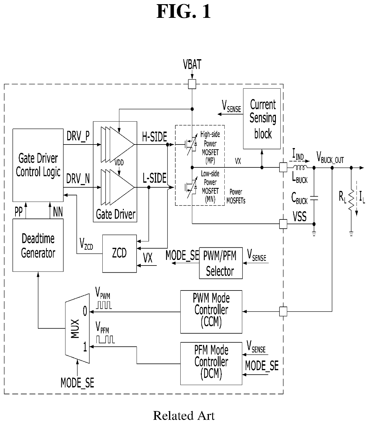
Recently, in the case of a DC-DC converter in a mobile device, the discontinuous current mode (DCM) becomes an issue because it operates based on a small inductor (LBUCK) and a low load (RL).
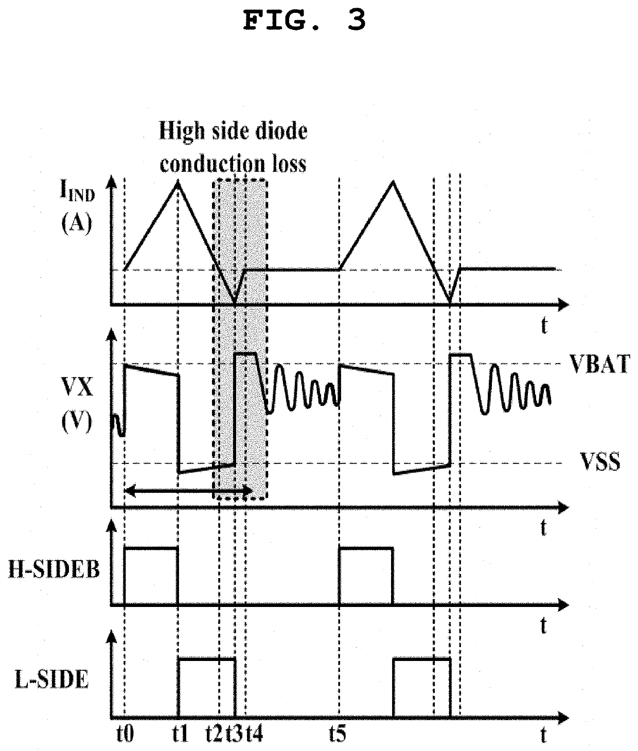
In the discontinuous current mode operation of the DC-DC converter, when the current of the inductor deviates from a zero current point or reverse current blocking point, reverse current is generated through NMOS diode conduction or the PMOS diode conduction, and thus an efficiency deterioration problem occurs.
In contrast, in the case of a DC-DC converter that supplies low power, efficiency may be degraded or an operational problem may occur.
However, the current consumption of the DC-DC converter that supplies low power is increased, and thus a problem arises in that the efficiency of the DC-DC converter is degraded.
Similarly, in order to increase the operation speed of the comparator, it is necessary to increase power consumption, and thus a problem arises in that the efficiency of the DC-DC converter that supplies low power is degraded.
Although low-power operation is possible through digital operation, a problem arises in that efficiency reduction is increased when a reverse current blocking point is not accurately detected.
In this related art, the voltage of a VX node is sampled using only a plurality of delay signals based on a second switching signal D2, and thus a problem arises that an error corresponding to the time delay generated by a delay circuit is inherent therein.

Method used


Image

  • Low-power DC-DC converter capable of preventing reverse current with digital operations and method of operating the same
  • Low-power DC-DC converter capable of preventing reverse current with digital operations and method of operating the same
  • Low-power DC-DC converter capable of preventing reverse current with digital operations and method of operating the same

Examples


Embodiment Construction

[0045]The above and other objects and features of the present invention will be apparent from the following embodiments that will be described with reference to the accompanying drawings.

[0046]The embodiments of the present invention will be described in detail below with reference to the accompanying drawings. In the following description of the present invention, when it is determined that a detailed description of a related well-known configuration or function may make the gist of the present invention obscure, the detailed description will be omitted.

[0047]The accompanying drawings and the embodiments are intended to facilitate understanding of the present invention with a focus on specific functions, operations, and configurations. In order to facilitate the above understanding, the accompanying drawings and the embodiments may be partially exaggerated or reduced in size. However, the spirit of the present invention should not be limited by the exaggerated or reduced specificat...


PUM


Abstract

A low-power direct current-direct current (DC-DC) converter includes a capacitor, an inductor electrically connected to the capacitor, a first switch configured to be turned on for a first switching interval and supply energy from an input power source to the inductor for the first switching interval, a second switch configured to be turned on for a second switching interval and electrically connect the inductor and a ground terminal for the second switching interval, and a switching control circuit configured to generate first and second switching signals. The switching control circuit is further configured to generate a first sample signal by sampling the voltage level of a first node, and to determine, responding to the first sample signal in time domain, an pulse width adjustment adapted to adjust at least one of the length of a second switching interval and the length of a common blocking interval.

Description

CROSS-REFERENCE TO RELATED APPLICATION[0001]This application claims under 35 U.S.C. § 119(a) the benefit of Korean Patent Application No. 10-2018-0008376 filed on Jan. 23, 2018, which is incorporated herein by reference.TECHNICAL FIELD[0002]The present invention relates generally to a highly efficient low-power DC-DC converter and a method of operating the low-power DC-DC converter, and more specifically to a low-power DC-DC converter having a digital self-tracking zero current detection function and a method of operating the low-power DC-DC converter.BACKGROUND ART[0003]Recently, with the development of mobile devices, the run time of a battery has become a significant issue. The run time of a portable battery is closely related to the low-power operation and efficiency of a power supply circuit. Accordingly, the optimization of the low-power operation of the power supply circuit and the improvement of the efficiency of the power supply circuit are required. In order to optimize lo...

Claims


Application Information

Patent Timeline
Patent Type & Authority Patents(United States)
IPC IPC(8): H02M3/158H02M1/38H02M1/00H02M1/088
CPCH02M3/158H02M1/088H02M1/38H02M3/1588H02M1/0048Y02B70/10H02M1/08H02M3/157
Inventor KIM, HONG JINHONG, SUK KYUNKIM, HYUN KYUOH, EUNGYUN, SUK
Owner ABOV SEMICON
Why Eureka
Try Eureka