Circuit and method for shunt current sensing

a current sensing and circuit technology, applied in the direction of current measurements only, measurement devices, instruments, etc., can solve the problems of reducing battery life, sensing works properly, damage to batteries, etc., to increase versatility, increase precision and robustness, and high precision

Active Publication Date: 2021-08-24
KONGSBERG INC
View PDF16 Cites 1 Cited by
  • Summary
  • Abstract
  • Description
  • Claims
  • Application Information

AI Technical Summary

Benefits of technology

[0014]The circuits and methods provide high precision shunt current sensing for all switching (fast, slow, constant) speeds (dI / dt) of the shunt resistor current. The circuit thereby provides increased versatility because the circuit can be utilized for high-frequency current switching schemes, such as PWM, multiphase, and DC / DC power switching applications. Thus, systems utilizing the circuit can operate at much higher frequencies than previously practical.
[0015]Filtering the shunt current with the first amplifier (UI) such that the output voltage produced by the current sense amplifier (U2) is substantially proportional to the shunt current provides tremendous benefit. The output voltage of the current sense amplifier closely resembles (directly or inversely) the shunt current and is free of undesired artifacts on the voltage across the shunt resistor. That is, the output voltage is without parasitic voltage peaks, unwanted oscillations, and ringing. This provides increased precision and robustness in the output voltage produced by the current sense amplifier.
[0016]Furthermore, the reduction of such voltages peaks and ringing in the amplifier output voltage virtually eliminates any setting time because the phase current stabilizes rapidly. As such, sampling or measurement of the phase current may be performed at any desired time. This further allows the circuit and method to effectively handle load impulses in high frequency current switching sensing because the setting time is virtually eliminated. In other words, the load current impulse time exceeds the setting time because the setting time is substantially reduced to zero.
[0017]Therefore, the techniques described herein eliminate the need to lower the PWM frequency to lower the rate of change of the current or to set a special current detection period for to compensate for the load current impulse time. Those skilled in the art appreciate that the circuit and method may provide additional advantages beyond those described herein.

Problems solved by technology

Overcharging of the battery may damage the battery or reduce battery life.
One major limitation in such conventional shunt current sensing techniques is that sensing works properly only when the current through the shunt resistor is constant or changes with only low or minimal speed (dI / dt).
Such parasitic inductance reactions cause voltages spikes in the shunt resistor voltage and LC resonance reactions cause unwanted oscillations in the shunt resistor voltage.
This, in turn, disrupts the output voltage produced by the current sense amplifier.
Notwithstanding these issues, conventional circuits rely on the output voltage waveform to be an amplified version of the shunt resistor voltage waveform, thereby exacerbating the problem.
Furthermore, a voltage pulse waveform outputted by the shunt resistor distorts during a certain period after a rise due to ringing resulting from the switching.
The setting time can be many microseconds and decreases effectiveness of the sensing circuit.
However, lowering the PWM frequency is impossible or impractical in many cases.
Unfortunately, setting the special current detection period disturbs PWM control flow and increases torque ripple.
Such conditions are unacceptable in certain systems, such as electronic power steering (EPS) systems, and the like.

Method used


Image

  • Circuit and method for shunt current sensing
  • Circuit and method for shunt current sensing
  • Circuit and method for shunt current sensing

Examples


Embodiment Construction

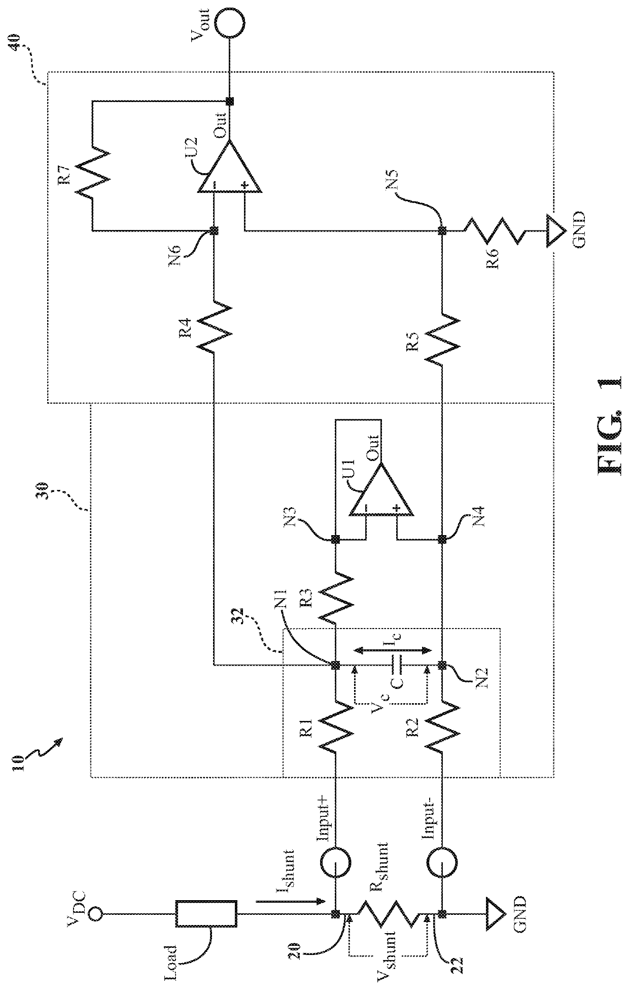
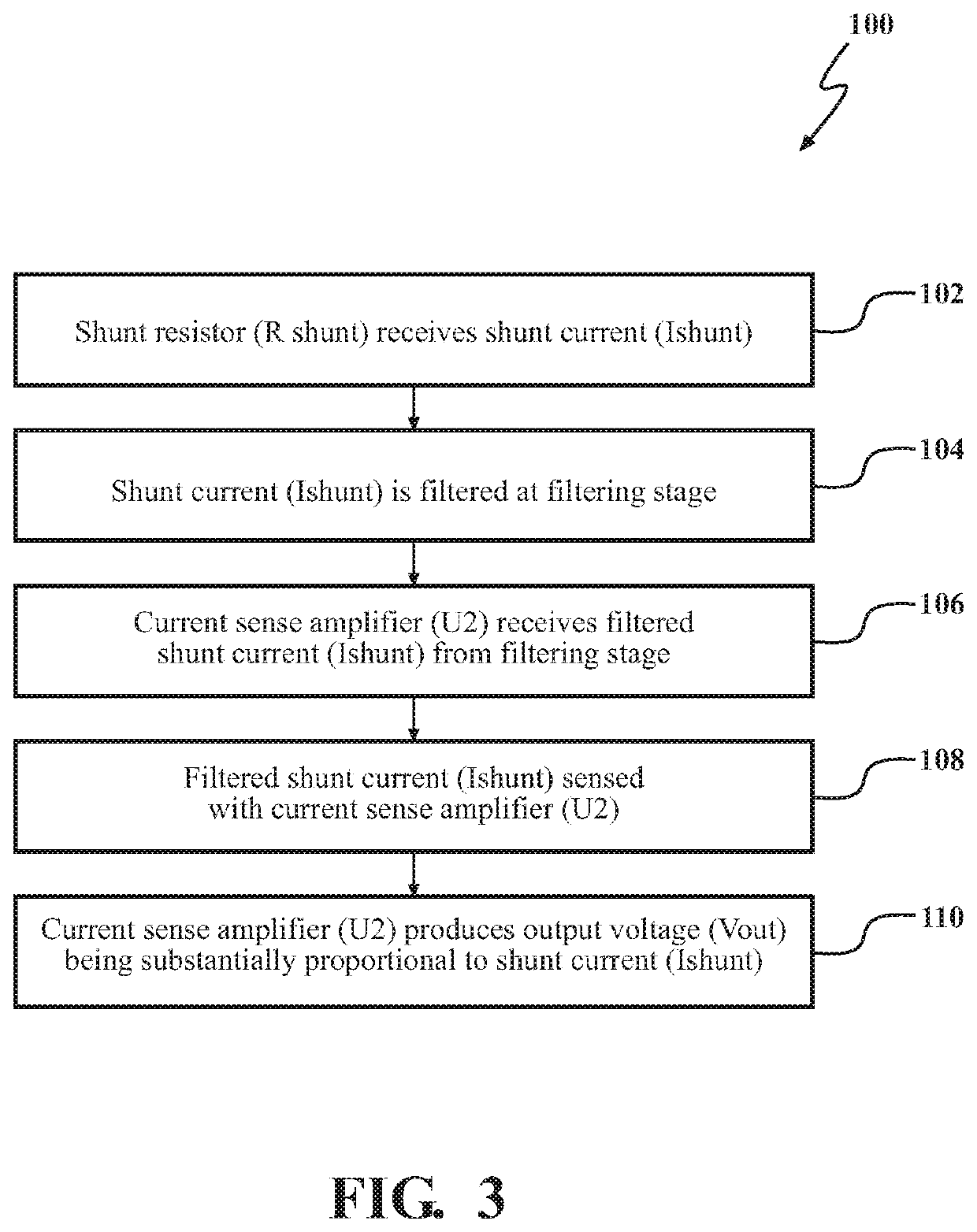
[0024]Referring to the Figures, wherein like numerals indicate like or corresponding parts throughout the several views, a circuit 10 and a method 100, 200 of operating the same are provided.

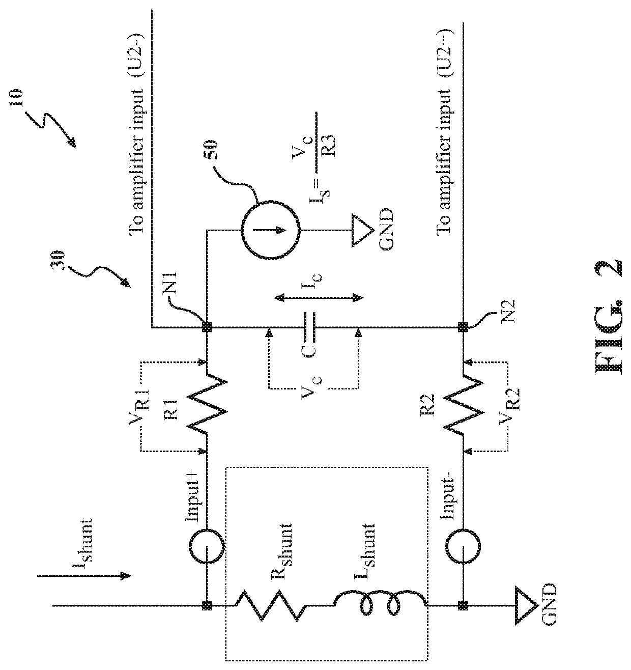
[0025]The circuit 10 is utilized for shunt current sensing. As such, the circuit 10 may also be referred to as a shunt current sensing circuit. Generally, shunt current sensing involves measuring current through a shunt resistor (Rshunt), as shown in FIG. 1. The shunt resistor (Rshunt) receives a shunt current (Ishunt) that flows through the shunt resistor (Rshunt).

[0026]The shunt resistor (Rshunt) is disposed in series with a load (L). This allows current flowing through the load (L) to also flow through the shunt resistor (Rshunt). As such, the shunt resistor (Rshunt) effectively senses the load (L) current. In this sense, the shunt resistor (Rshunt) is effectively a current-sense resistor. The shunt current (Ishunt) is analogous to the load current. The shunt current (Ishunt) may have any amp...


PUM


Abstract

Circuits and methods relating to shunt current sensing are provided. A shunt current sensing circuit comprises a shunt resistor for receiving a shunt current. A filtering stage is connected to the shunt resistor and is configured to filter the shunt current. A current sense amplifier is connected to the filtering stage and is configured to receive the filtered shunt current from the filtering stage. The current sense amplifier is configured to sense the filtered shunt current to produce an output voltage. The filtering stage is configured to filter the shunt current such that the output voltage produced by the current sense amplifier (U2) is substantially proportional to the shunt current.

Description

CROSS REFERENCE TO RELATED APPLICATIONS[0001]This application is the U.S. National Stage of International Patent Application No. PCT / IB2016 / 051210, filed on Mar. 3, 2016, the disclosure of which is hereby incorporated by reference.BACKGROUND1. Field of the Invention[0002]The subject invention relates to circuits and methods for shunt current sensing.2. Description of Related Art[0003]Electrical or electronic systems commonly sense and control electrical current flow. For example, a battery charger controls a charging current provided to a charging battery. Overcharging of the battery may damage the battery or reduce battery life. A precision current sense amplifier is typically employed in the battery charger circuit to monitor charging current provided to the battery. Typically, a shunt resistor is placed between the battery charger circuit and the battery for monitoring the charging current. The voltage across the shunt resistor is measured and the current sense amplifier amplifie...

Claims


Application Information

Patent Timeline
Patent Type & Authority Patents(United States)
IPC IPC(8): G01R15/14G01R19/00
CPCG01R15/146G01R19/0092G01R1/203
Inventor PANINE, NIKOLAI
Owner KONGSBERG INC
Why Eureka
Try Eureka